Portable communication device comprising an antenna

a communication device and portable technology, applied in the direction of antennas, antenna supports/mountings, radiating element structural forms, etc., can solve the problems of difficult to provide appropriate technical specifications for 2.4 ghz antennas, and achieve good esd protection, good controllable (reproducible) capacitive coupling, and good esd protection

Active Publication Date: 2014-03-11
EPOS GROUP AS
View PDF14 Cites 8 Cited by
  • Summary
  • Abstract
  • Description
  • Claims
  • Application Information

AI Technical Summary

Benefits of technology

[0010]This has the advantage of providing an alternative wireless interface for a communication device.
[0015]In an embodiment, the first patch is electromagnetically coupled to an underlying driven antenna part, the first patch thus becoming a parasitic patch of the antenna. Because the first patch form part of the housing of the communication device, it will be exposed to human handling, but the present configuration of the antenna has the advantage that the antenna is less sensitive to such handling (e.g. in the form of a hand of the person using the device) because the driven antenna is electromagnetically shielded by the parasitic patch. An antenna structure comprising a parasitic patch and an underlying driven antenna part (e.g. a quarter wavelength patch or a half wavelength loop antenna part) and a ground plane is thus advantageous for handheld portable devices (e.g. headset applications) compared to a single patch antenna solution.
[0023]In an embodiment, the shorted loop is the driven element of the antenna, i.e. the loop element is connected to transceiver circuitry of the wireless interface. An advantage of using a (planar) loop instead of a patch as the driven element of the antenna is that it provides an increased flexibility in the localization of the electrical connection to the transceiver (no or less location (symmetry) considerations to comply with). In an embodiment, the loop antenna is driven at a point along the periphery of the loop. In an embodiment, the loop antenna is driven at a point located a predefined distance from a point of connection of the loop antenna to the ground plane. In an embodiment, the distance between a driving point and a grounding point is in the range from 0.1·(λc / 2) to 0.3·(λc / 2), such as in the range from 0.15·(λc / 2) to 0.25·(λc / 2), e.g. around 0.2·(λc / 2).
[0024]In an embodiment, the loop opening of the half-wavelength loop antenna is adapted to allow other constructional parts of the device, e.g. electronic components, to extend through the opening, thereby allowing a more compact device structure. Similarly, in an embodiment, the outer periphery of the half-wavelength loop antenna is adapted in form to comply with other restrictions of the device, e.g. to allow to allow other constructional parts of the device (e.g. components extending through the housing, e.g. a button) to be located along its periphery.
[0046]In a particular embodiment, the first patch is capacitively coupled to the shorted loop. Preferably, the capacitance between the shorted loop and parasitic patch element(s) is adapted to represent an electrical RF-short circuit at the operating wavelength of the wireless interface. Alternatively, a direct galvanic connection, e.g. implemented by one or more gold contacts, can be used. The capacitive coupling has the advantage of providing a good ESD protection (ESD=ElectroStatic Discharge) and is achieved by adapting the area of the terminal(s) connecting to the shorted loop and facing the first parasitic patch, the distance between the terminal(s) and the first parasitic patch, and the kind of dielectric material between terminal(s) and parasitic patch. The dielectric material and its thickness are preferably adapted to be able to withstand an electrostatic voltage larger than 3 kV, such as larger than 5 kV.
[0047]In a particular embodiment, the fourth layer comprises a polymer, e.g. in the form of an adhesive tape. In an embodiment, the fourth layer comprises a polyimide layer of a flexprint. In an embodiment, the fourth layer comprises an ESD protective tape, e.g. a polyimide tape (e.g. Kapton® from Dupont). In an embodiment, an ESD tape is used as insulating layer between a connection to the shorted loop and the parasitic patch of the fifth layer. This has the advantage of providing a good, controllable (reproducible) capacitive coupling between the (driven) shorted loop and the parasitic patch.

Problems solved by technology

The provision of sufficient bandwidth and reasonable efficiency of an antenna in a portable communication device is a general problem.
Thus for a state of the art communication device having external dimensions less than 6 cm (e.g. headsets) and even less than 5 cm and often less than 2 cm or 1 cm (e.g. hearing instruments), it can in practice difficult to provide an antenna with appropriate technical specifications at 2.4 GHz (in view of the typical limited power supply of a portable (e.g. battery driven) communication device).

Method used


Image

  • Portable communication device comprising an antenna
  • Portable communication device comprising an antenna
  • Portable communication device comprising an antenna

Examples


Embodiment Construction

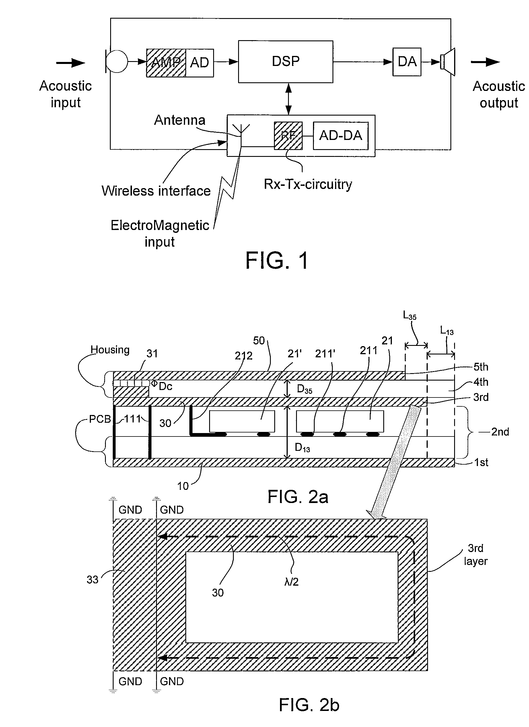
[0086]FIG. 1 shows a communication device comprising a wireless interface. The communication device, e.g. a headset, a protective earplug or a hearing instrument, comprises a microphone system (comprising one or more microphones) for converting an acoustic input sound to an electric input signal, an amplifier (AMP) and an analogue to digital converter (AD) for providing a digitized electric input signal representative of the acoustic sound. The communication device further comprises a signal processor (DSP) for processing the digitized electric input signal (e.g. for applying a frequency dependent gain to the signal according to a users' needs (e.g. in a hearing instrument) or for otherwise enhancing and / or encoding the input signal (e.g. in a headset)). The communication device further comprises a digital to analogue (DA) converter and an output transducer (here a speaker; in hearing aid applications often termed a ‘receiver’) for presenting a signal from the signal processor to a ...


PUM


Abstract

The invention relates to a communication device comprising a wireless interface for enabling wireless transmission and / or reception at a predefined wavelength λc to be established. The object of the present invention is to provide an antenna suitable for wireless communication in a portable communication device. The problem is solved in that the communication device comprises a housing having an electrically conductive part, the wireless interface comprising an antenna comprising a first quarter wavelength patch and a ground plane comprising an electrically conductive material, the first quarter wavelength patch being at least partially constituted by said electrically conductive part of the housing. This has the advantage of providing an alternative wireless interface for a communication device. The invention may e.g. be used in portable communication devices with a wireless interface for communication with another device, in particular in a headset or a headphone or an active earplug.

Description

CROSS REFERENCE TO RELATED APPLICATIONS[0001]This nonprovisional application claims the benefit under 35 U.S.C 119(e) to U.S. Provisional Application No. 61 / 244,091 filed on Sep. 21, 2009 and under 35 U.S.C 119(a) to EP 09170802.4 filed on Sep. 21, 2010. The entire contents of the above applications are hereby incorporated by reference into the present application.TECHNICAL FIELD[0002]The present invention relates to communication devices, in particular to antennas for communication devices. The invention relates specifically to a communication device comprising a wireless interface for enabling wireless transmission and / or reception at a predefined wavelength λc to be established.[0003]The invention may e.g. be useful in applications such as portable communication devices with a wireless interface for communication with another device, in particular in a headset or a headphone or an active earplug.BACKGROUND ART[0004]The provision of sufficient bandwidth and reasonable efficiency o...

Claims


Application Information

Patent Timeline
Patent Type & Authority Patents(United States)
IPC IPC(8): H01Q1/24
CPCH01Q1/244H01Q9/0457
Inventor HILLERSBORG, PER
Owner EPOS GROUP AS
Why Eureka
Try Eureka