
Control apparatus of vehicle incorporating automatic transmission

Inactive Publication Date: 2006-02-23
TOYOTA JIDOSHA KK
View PDF4 Cites 5 Cited by
  • Summary
  • Abstract
  • Description
  • Claims
  • Application Information

AI Technical Summary

Benefits of technology

[0015] According to the present invention, if an operator executes a special operation (which is not executed when normally driving, and which is done using a shift lever) at a dealer or the like, a metering mode for adjusting an amount of hydraulic fluid of an automatic transmission is entered. The metering mode is realized in a state where an internal combustion engine is kept to be actuated (and while the vehicle is parking). A pump for circulating the hydraulic fluid of the automatic transmission is being actuated, and the hydraulic fluid is circulating in the automatic transmission. Since the hydraulic fluid greatly changes its behavior depending on its viscosity, and the viscosity is dependent on temperature, the temperature of the hydraulic fluid suitable for the metering work is set in advance. The speed of an internal combustion engine is controlled (for example, to maintain the speed) when the temperature is attained. Thus, the internal combustion engine can be controlled so that the hydraulic fluid of the automatic transmission attains a state suitable for the metering work. Thus, the internal combustion engine is controlled, and when the temperature suitable for metering is reached, information indicative of the state suitable for the metering work is attained is output by an output unit, so that the operator can recognize. The operator meters the hydraulic fluid of the automatic transmission based on the output information. As a result, the control apparatus of a vehicle incorporating an automatic transmission that is capable of precisely adjusting the oil level of the automatic transmission can be provided.
[0017] According to the present invention, the speed of the internal combustion engine is maintained when the temperature of the hydraulic fluid attains the temperature not higher or lower than the temperature suitable for the metering work, so that the temperature can be maintained.
[0019] According to the present invention, the speed of the internal combustion engine is maintained when the temperature of the hydraulic fluid attains the temperature range not higher or lower than the temperature suitable for the metering work, so that the temperature range can be maintained.
[0021] According to the present invention, as an operator can perform a metering work when the hydraulic fluid of an automatic transmission is at the temperature suitable for the metering work, the oil level of the automatic transmission can precisely be adjusted, and a control apparatus of a vehicle incorporating an automatic transmission can be provided. Additionally, as information (information indicating that the state suitable for the metering work is attained) is output so that the operator can recognize, the operator can start the work immediately after the state suitable for the metering work is attained.

Problems solved by technology

On the other hand, with an excessive amount of oil, if the oil level is raised by expansion when, for example, the oil is at a high temperature, the oil is agitated by a rotary member such as a clutch drum of a gear type transmission mechanism.
This increases the mechanical loss and further raises the oil temperature.
Thus, the durability of the automatic transmission may be deteriorated and oil blow out from a breather may be incurred.
However, as the oil deteriorates with age, an oil change is also done at a dealer when the vehicle is used over a long period.
However, such a method requires a course for driving the vehicle, as well as many steps.
If the engine speed changes in such a state, an amount of oil sticking inside (when the hydraulic fluid is low in temperature and high in viscosity, it sticks to a housing or the like in the transmission mechanism and would not return to an oil pan) and / or a hydraulic fluid temperature do not attain desirable values.
Accordingly, the oil level fluctuates and precise adjustment of the oil level is difficult.

Method used


Image

  • Control apparatus of vehicle incorporating automatic transmission
  • Control apparatus of vehicle incorporating automatic transmission
  • Control apparatus of vehicle incorporating automatic transmission

Examples


Embodiment Construction

[0026] In the following, referring to the drawings, an embodiment of the present invention is described. In the following description, identical components are denoted by an identical reference character. Their name and function are also identical. Accordingly, detailed description thereof is not repeated.

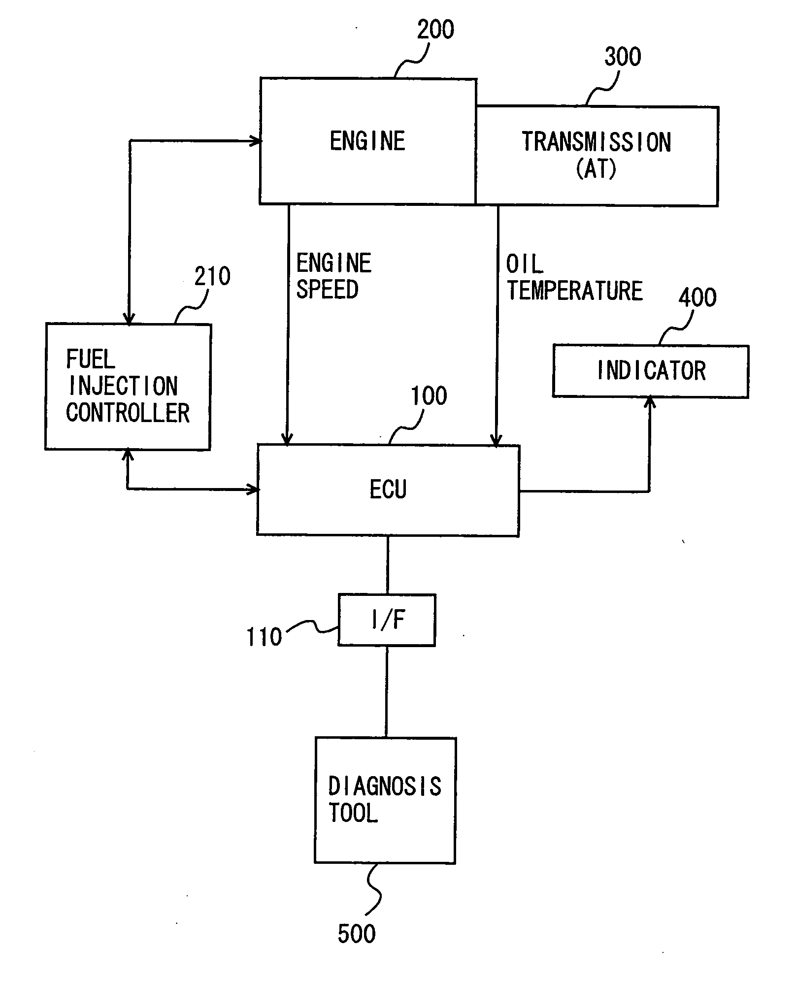
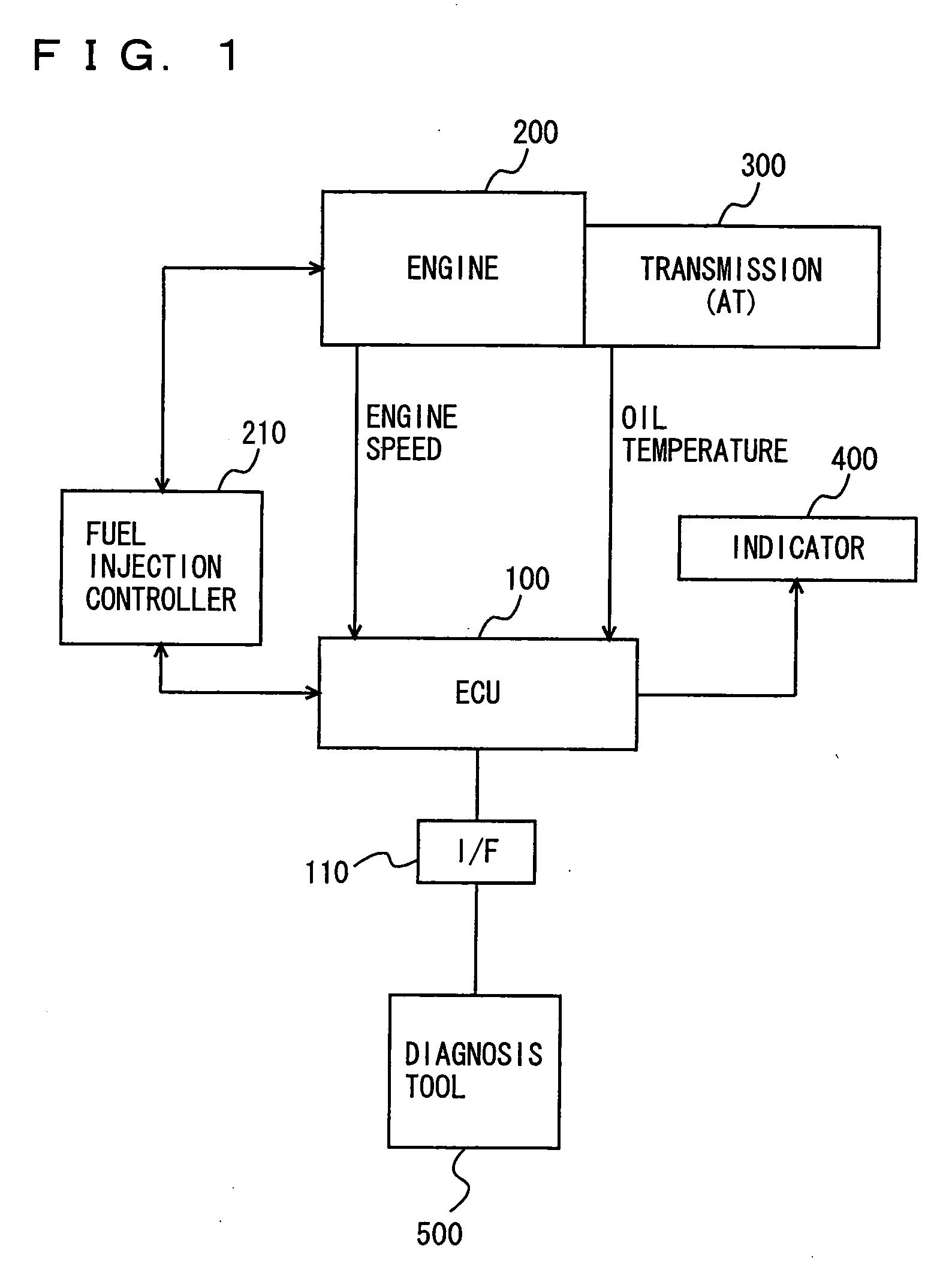
[0027] Referring to FIG. 1, a control block diagram of a power train controlled by an ECU (Electronic Control Unit) that is a control apparatus according to the present embodiment is described.

[0028] The control apparatus according to the present embodiment is implemented by an ECU 100 shown in FIG. 1. ECU 100 solely embodies two functions of an engine ECU and an ECT (Electronically Controlled Automatic Transmission)_ECU. ECU 100 mainly controls an engine 200 and a transmission (AT) 300 connected to an output shaft of engine 200.

[0029] Engine 200 may be a known petrol or diesel engine, and it is not specifically limited. Transmission 300 may be an automatic transmission that use...


PUM


Abstract

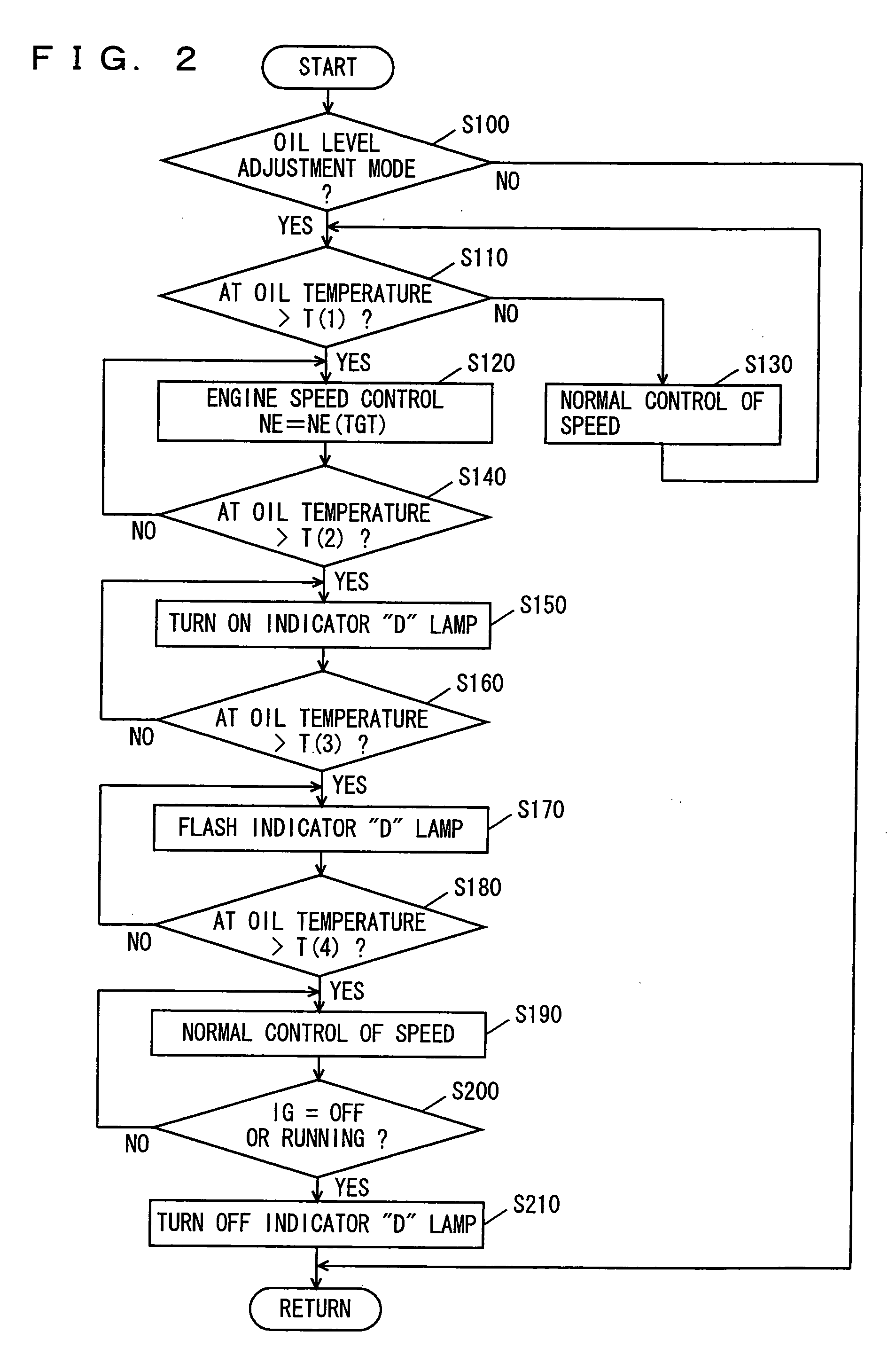
An ECU executes a program including the steps of, when an oil level adjustment mode is attained, executing control of the engine speed if an AT oil temperature is higher than an oil temperature threshold value T(1), turning on a “D” lamp of an indicator if the AT oil temperature is higher than an oil temperature threshold value T(2) and the AT temperature is lower than an oil temperature threshold value T(3), flashing the “D” lamp of the indicator if the AT oil temperature is higher than the oil threshold value T(3), and executing normal engine speed control if the AT oil temperature is higher than an oil temperature threshold value T(4).

Description

[0001] This nonprovisional application is based on Japanese Patent Application No. 2004-227912 filed with the Japan Patent Office on Aug. 4, 2004, the entire contents of which are hereby incorporated by reference. BACKGROUND OF THE INVENTION [0002] 1. Field of the Invention [0003] The present invention relates to a control apparatus of a vehicle, and particularly, to a technique for controlling an internal combustion engine of a vehicle when adjusting an amount of hydraulic fluid of an automatic transmission in the vehicle incorporating the automatic transmission. [0004] 2. Description of the Background Art [0005] Among automobiles, particularly many passenger cars employ an automatic transmission (AT) as a transmission. The automatic transmission is constituted by a torque converter and a transmission mechanism (irrespective of whether it is a stepped transmission using gears or the like or a continuously variable transmission using a belt of the like), wherein the torque converter...

Claims


Application Information

Patent Timeline
IPC IPC(8): G06F17/00F02D45/00F16H59/72F16H61/02F16H63/50
CPCF16H57/0413Y10T477/653F16H59/72F16H57/0449
Inventor CHIDA, RYUJIMATSUO, KENJINAKADA, HIROFUMIINAGAWA, TOMOKAZUNAKAMURA, KAZUAKI
Owner TOYOTA JIDOSHA KK
Learn More