Measuring head

a measuring head and head technology, applied in the field of measuring heads, can solve the problems of cumbersome assembly and a large overall head size, cumbersome assembly and zero point adjustment, and a large amount of time and effort, and achieve the effects of increasing the flexibility of the measuring head, prolonging life, and maintaining accuracy

Inactive Publication Date: 2006-03-02
TOKYO SEIMITSU
View PDF3 Cites 25 Cited by
  • Summary
  • Abstract
  • Description
  • Claims
  • Application Information

AI Technical Summary

Benefits of technology

[0014] Preferably, the measuring head further comprises a regulating device which regulates an amount of swing of the base lever and variably controlling an amount of travel of the measurement lever. When the measuring head with the amount of deflection (amount of travel) of the measurement lever predefined by closing operation of the fastening member is used to measure another workpiece that has a different amount of travel than that of the head, the regulating device may thus be used to regulate the amount of swing of the base lever and variably control the amount of travel. The amount of travel may thus mechanically be controlled by the regulating device, increasing flexibility of a measuring head.
[0015] Preferably, the clamp mechanism is sealed to avoid entrance of foreign matters from outside. The clamp mechanism is thus sealed to avoid the entrance of foreign matters from the outside, such as chips, abrasive particles and coolant: it is effective to maintain accuracy, extend life and avoid faulty operation, etc. of a clamp mechanism.
[0016] Preferably, the fastening member is configured to be rotated manually or through a tool. The fastening member thus has one arrangement that can manually be rotated, for example is provided with a lever portion, or another arrangement that can be rotated through a tool, for example has a hole (hexagonal hole) formed to allow a hexagonal bar spanner (hexagonal wrench) to fit therein, facilitating manipulation.
[0017] Preferably, the fastening member comprises a cam, and an engaging device is provided which holds an amount of rotation of the cam in a stepped manner. The rotation of a cam thus allows the measurement lever to deflect, and an engaging device which holds the amount of rotation of the cam in a stepped manner is provided, facilitating control of the amount of deflection of the measurement lever, i.e. variable control of the amount of travel.

Problems solved by technology

The zero point adjustment must be made each time the dimensions of the measured workpiece are changed, requiring a large amount of time and effort.
Although the measuring head with the above arrangement can accomplish the zero point adjustment, it suffers from the disadvantage that it has a complex mechanism and a large number of parts, leading to cumbersome assembly and a large size of the overall head.
The measuring head with the above arrangement, however, also suffers from the disadvantage that it has a complex mechanism for the zero point adjustment, leading to cumbersome assembly and zero point adjustment.

Method used


Image

  • Measuring head
  • Measuring head
  • Measuring head

Examples


first embodiment

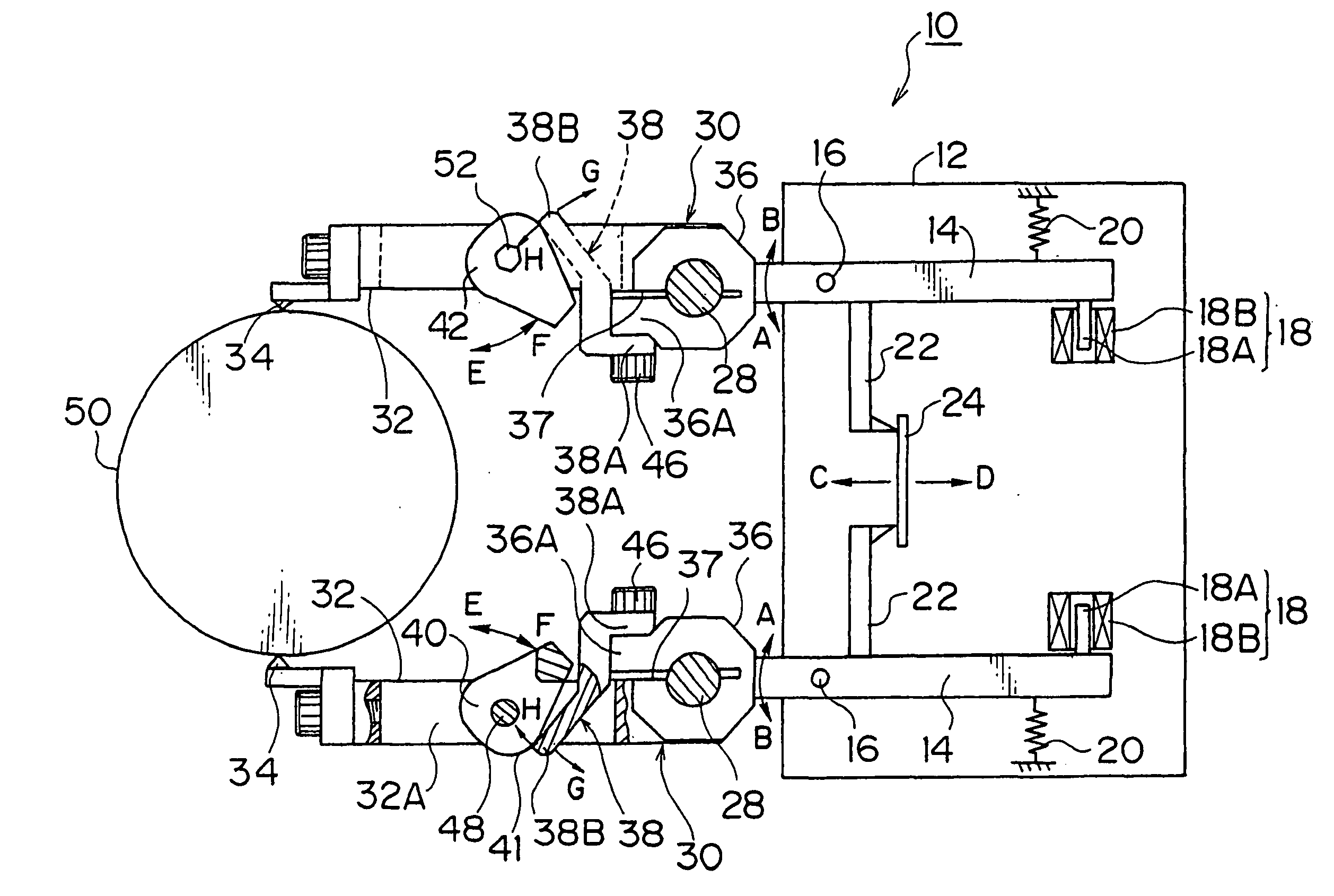
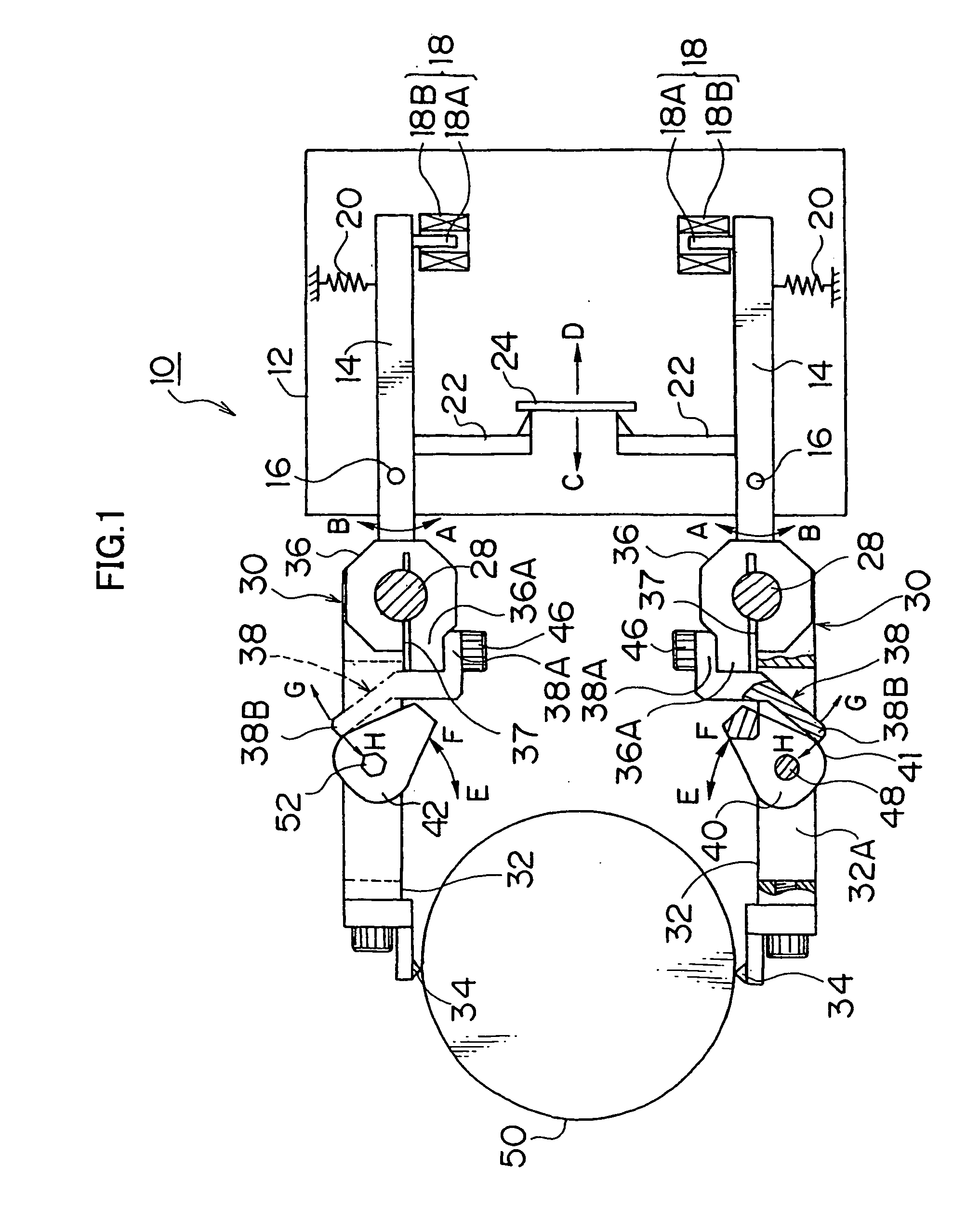
[0033] A measurement lever 32 is swingably provided to the swinging support shaft 28 via the clamp mechanism 30 of a A contact 34 is mounted at a tip end of the measurement lever 32, and the contact 34 is abutted against a workpiece 50, which is a measured object, for measuring the outer diameter of the workpiece 50.

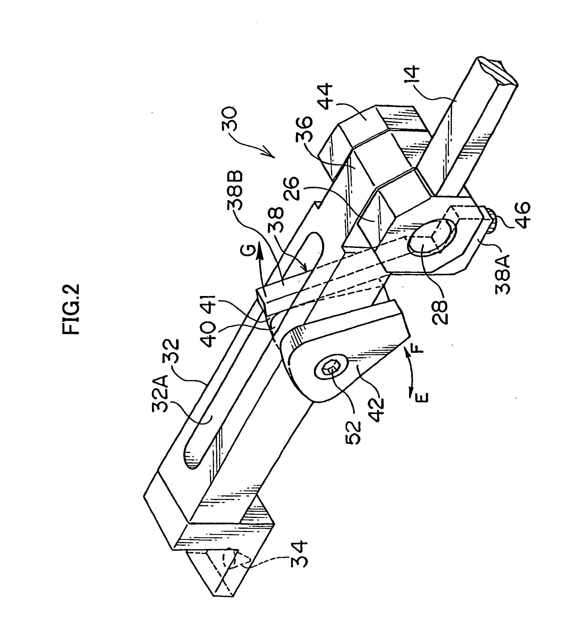
[0034] The clamp mechanism 30 is composed of a bearing member 36, an arm 38, a cam plate 40 or a fastening member, a lever 42, and the like. Although the lever 42 and cam plate 40 use substantially identical shapes in FIG. 2, a lever 42 in other shape may also be used.

[0035] The bearing member 36 is a bearing that allows the swinging support shaft 28 to rotatably fit therein, as shown in FIG. 1, and is formed at an base end of the measurement lever 32 and has a slit portion 37 formed therein. The bearing member 36 is fastened to the swinging support shaft 28 by resiliently deforming the slit portion 37 in a closing direction thereof. This unrotatably secures the measur...

second embodiment

[0052] In the mechanism of the clamp mechanism 60 of the second embodiment, rotating the cam plate 62 to fasten the bearing member 36 to the swinging support shaft 28 allows a restoring force (or a force caused by reaction) of the bearing member 36 to transfer from the bearing member 36 through the arm 38, cam plate 62 and shaft 48 to the measurement lever 32. The restoring force works from the arm 38 to the cam plate 62 in a direction indicated by an arrow H in FIG. 4, so that the measurement lever 32 deflects by an amount that equals to the amount of front travel.

[0053] In a measuring head having the clamp mechanism 60 of the second embodiment, therefore, the zero point position is automatically set by fastening the lever 64, facilitating the zero point position setting.

[0054]FIG. 5(a) is a conceptual view illustrating a construction of a clamp mechanism 70 of a third embodiment, and FIG. 5(b) is a cross-sectional view taken along the line 5(b)-5(b) in FIG. 5(a). Similar members ...

third embodiment

[0057] The third embodiment is characterized by the arrangement in that the fastening member comprises a cam plate, and an engaging device which holds the amount of rotation of the cam plate in a stepped manner is provided. The engaging device 78 is composed of a gear-shaped portion 75 formed on a peripheral surface of the cam plate 72, and a ball plunger 76 fastened to the measurement lever 32.

[0058] Specifically, the engaging device 78 is arranged as described below. A through-hole 32B is provided from an end surface of a tip end of the measurement lever 32, and a female screw is provided in the through-hole 32B. The ball plunger 76 that is circumferentially provided with a male screw for screwing into the female screw is screwed into the through-hole 32B in a tip end of the measurement lever 32, and positioned to engage the gear-shaped portion 75 of the cam plate 72 in the tip thereof.

[0059] The ball plunger 76 has a retractable ball 76A biased by a spring, which is not shown, i...


PUM


Abstract

According to the measuring head, the zero point and the amount of front travel settings are facilitated. Firstly, the amount of front travel is set by allowing contacts 34, 34 to abut a master 50. Then, rotating the lever 42 in a direction indicated by an arrow E, or a close position, causes the bearing member 36 to be fastened to the swinging support shaft 28. At this time, a restoring force, or a force caused by reaction, of the bearing member 36 transferred from the bearing member 36 through the arm 38, cam plate 40 and shaft 48 to the measurement lever 32 causes the measurement lever 32 to deflect by an amount that equals to the amount of front travel, and therefore from the position where the amount of front travel is set to the zero point position. This automatically sets the zero point position.

Description

TECHNICAL FIELD [0001] The present invention relates to a measuring head, and particularly to a measuring head applied to a gauge apparatus for measuring the shape and dimensions of a workpiece during processing and to an inspection and measurement apparatus for measuring the shape and dimensions of a workpiece after the processing. BACKGROUND ART [0002] Comparative measurement of an outer diameter of a workpiece with a certain design dimension initially requires the zero point adjustment of a detector using a master of the dimension. The zero point adjustment must be made each time the dimensions of the measured workpiece are changed, requiring a large amount of time and effort. [0003] A measuring head disclosed in Japanese Patent Examined Application Publication No. 6-48161, as shown in FIG. 8, is mainly composed of a base lever 2 including a detector 1 at a base end thereof, a measurement lever 3 including a contact 3a at a tip end thereof, a rotatable fulcrum shaft 4 pivotally s...

Claims


Application Information

Patent Timeline
Patent Type & Authority Applications(United States)
IPC IPC(8): G01B3/00G01B5/00G01B5/08G01B7/12
CPCG01B7/12G01B5/08G01B5/0004G01B5/12G01B7/13
Inventor KANAI, TAKAAKISAKAUE, TOMONORI
Owner TOKYO SEIMITSU
Why Eureka
Try Eureka