Adsorbing element

a technology of adsorption element and adsorption chamber, which is applied in the direction of separation of dispersed particles, chemistry apparatus and processes, and separation of separation processes, etc., can solve the problems of high molding cost, high air flow resistance, and inability to apply to the use where low air flow resistance is necessary, etc., and achieve the effect of effectively overcoming drawbacks

Inactive Publication Date: 2006-03-02
MAHLE FILTER SYST JAPAN CORP +1
View PDF9 Cites 26 Cited by
  • Summary
  • Abstract
  • Description
  • Claims
  • Application Information

AI Technical Summary

Benefits of technology

[0009] It is an object of the present invention to provide an improved adsorbing element which can

Problems solved by technology

Although a structure where granular and formed activated carbon or pulverized activated carbon is packed as it is in a container is simple, the air flow resistance is high; accordingly, it cannot be applied to the use where low air flow resistance is necessary.
However, since the molding cost is high and molds for molding into individual honeycomb shapes corresponding to devices such as deodorizing devices are necessary, in particular, it is not suitable for limited production of diversified products.
However, such the adsorbing sheet, being provided wi

Method used


Image

  • Adsorbing element
  • Adsorbing element
  • Adsorbing element

Examples


Embodiment Construction

[0028] Referring now to FIGS. 1 to 3 of the drawings, an embodiment of an adsorbing element according to the present invention will be discussed.

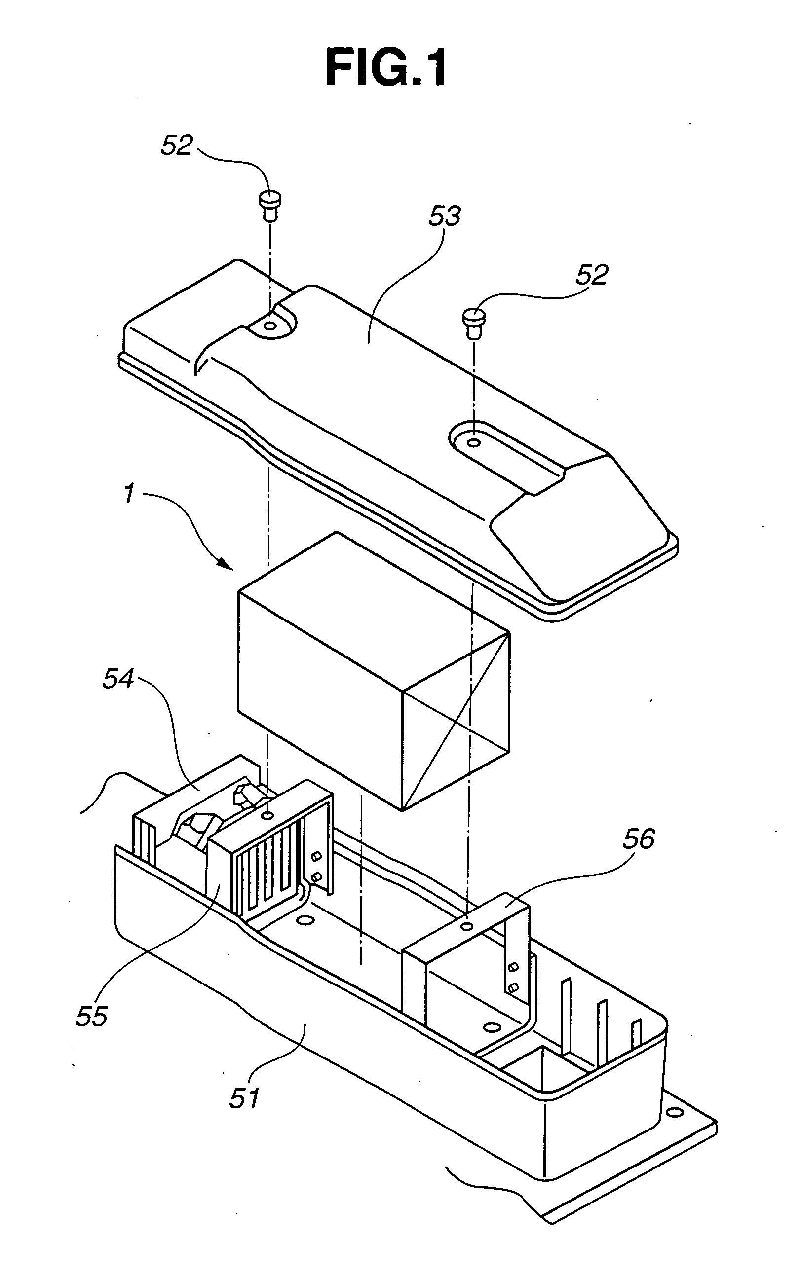
[0029]FIG. 1 is an exploded perspective view of a deodorizing device for a garbage drying processor in which an adsorbing element according to the invention is used. The deodorizing device includes a slender rectangular body 51 disposed in an exhaust path of a garbage drying processor (not shown). A cover 53 is attached to the body 51 with a screw 52 so as to cover a top surface opening of the body 51. At one end of the inside of the body 51, a blower unit 54 is attached to blow air. A rectangular columnar adsorbing element 1 according to the present invention is fixed and supported in series with the blower unit 54 through front and rear supporting metal fittings 55 and 56.

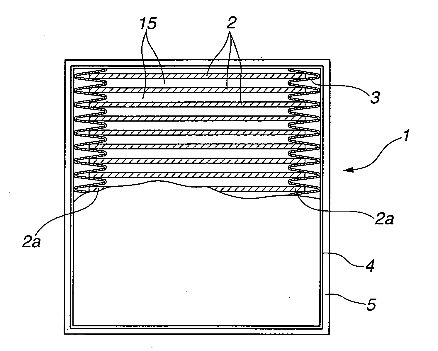
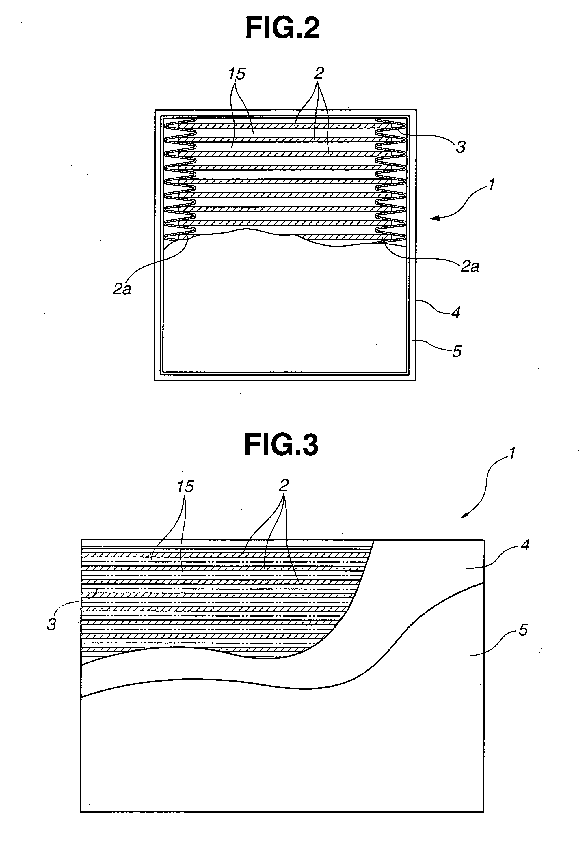
[0030]FIGS. 2 and 3 are, respectively, a front view and a side view of the adsorbing element 1. The adsorbing element 1 includes a plurality of rectangular adsorbing s...


PUM


Abstract

An adsorbing element for adsorbing and releasing a gas includes a plurality of adsorbing sheets. Each adsorbing sheet includes gas-permeable sheets such as non-woven fabrics or filter papers, and an adsorbing material filled between the gas-permeable sheets. First and second supporting members are provided such that each of them is formed of a paper-like sheet formed with a plurality of pleats which have straight trough lines. Each of the pleats of the first supporting member is located facing and spaced from each of the pleats of the second supporting member to form a pair of the facing pleats, defining a pair of facing trough portions. In this adsorbing element, the first and second side edges of each adsorbing sheet are located respectively at the pair of facing trough portions so that each adsorbing sheet is supported between the pair of the facing trough portions.

Description

BACKGROUND OF THE INVENTION [0001] 1. Field of the Invention [0002] The invention relates to an adsorbing element that adsorbs and releases foul odors, harmful gases or fuel gases. [0003] 2. Description of the Related Art [0004] JP-A-2003-24896 discloses a raw garbage processor in which raw garbage from homes is dried and processed under agitation while supplying hot air. In this kind of devices, in an exhaust path through which an exhaust gas flows from a dryer vessel, a deodorizing device is disposed to remove the foul odors. Japanese Patent No. 3,007,311, discloses as a deodorizing filter that is used in such a deodorizing device, a cylindrical structure in which a sheet material formed by intervening a pulp containing a deodorant and a water-absorbing polymer between a non-woven fabric and a resin film is wound in honeycomb. [0005] Furthermore, JP-A-2004-100691 relates to an evaporative fuel treatment apparatus that adsorbs a fuel component vaporized from a fuel tank of an autom...

Claims


Application Information

Patent Timeline
IPC IPC(8): B01D53/02
CPCB01D53/0407B01D53/0415B01D2253/102B01D2257/702B01D2257/80B01J20/28052B01D2259/4516B01D2259/4525B01J20/28033B01J20/28035B01J20/2805B01D2257/90
Inventor MARU, SHIGEO
Owner MAHLE FILTER SYST JAPAN CORP
Why Eureka
Try Eureka