Transportation system

a transportation system and transportation technology, applied in the field of transportation systems, can solve the problems of increasing reducing the degree of freedom of design with respect, and requiring huge bridge piers, so as to reduce the size and weight of the vehicle, increase the degree of freedom of design, and save the cost of construction.

Inactive Publication Date: 2006-03-02
SENYO INDS
View PDF4 Cites 18 Cited by
  • Summary
  • Abstract
  • Description
  • Claims
  • Application Information

AI Technical Summary

Benefits of technology

[0004] In view of the above-described problems, a primary concern of the present invention is to provide a transportation system having an advantage that a small-sized, light-weighted drive unit can be used as the drive unit mounted on a vehicle to achieve reductions in size and weight of the vehicle, thereby saving the cost for constructing the transportation system, and increasing the degree of freedom of design.
[0006] According to the above transportation system of the present invention, since the vehicle is accelerated by the propulsion supply unit provided in the vicinity of the station, it does not need to carry a large drive unit having the capability of providing a large propulsion force to accelerate the vehicle from a stopped condition to a required speed. Consequently, remarkable reductions in size and weight of the vehicle can be achieved. Therefore, even when a sufficient land area for constructing huge bridge piers for a conventional vehicle carrying the large drive unit thereon is not secured, the transportation system of the present invention can be actualized by constructing relatively small bridges piers for the small-sized, light-weighted vehicle. Thus, the present invention provides an increased degree of freedom of design with respect to the construction of the transportation system. Furthermore, impossible to overlook is a considerable reduction in the construction cost.
[0007] In the present invention, it is preferred that the propulsion supply unit of the transportation system is a linear-type accelerator for accelerating the vehicle by providing a propulsion force from a first magnet located on the track to a second magnet mounted on the vehicle. In this case, it is possible to smoothly accelerate the vehicle from the stopped condition to the required speed through a relatively short distance, and therefore give a comfortable ride quality to the passengers.

Problems solved by technology

When such a large drive unit is mounted in the vehicle, it leads to increases in size and weight of the vehicle.
Consequently, huge bridge piers are needed to support the rail and the vehicle.
This becomes a cause of lowering the degree of freedom of design with respect to the construction of a monorail system.
Furthermore, as larger the land area needed to construct the monorail system, the construction cost also becomes higher.

Method used


Image

  • Transportation system
  • Transportation system
  • Transportation system

Examples


first embodiment

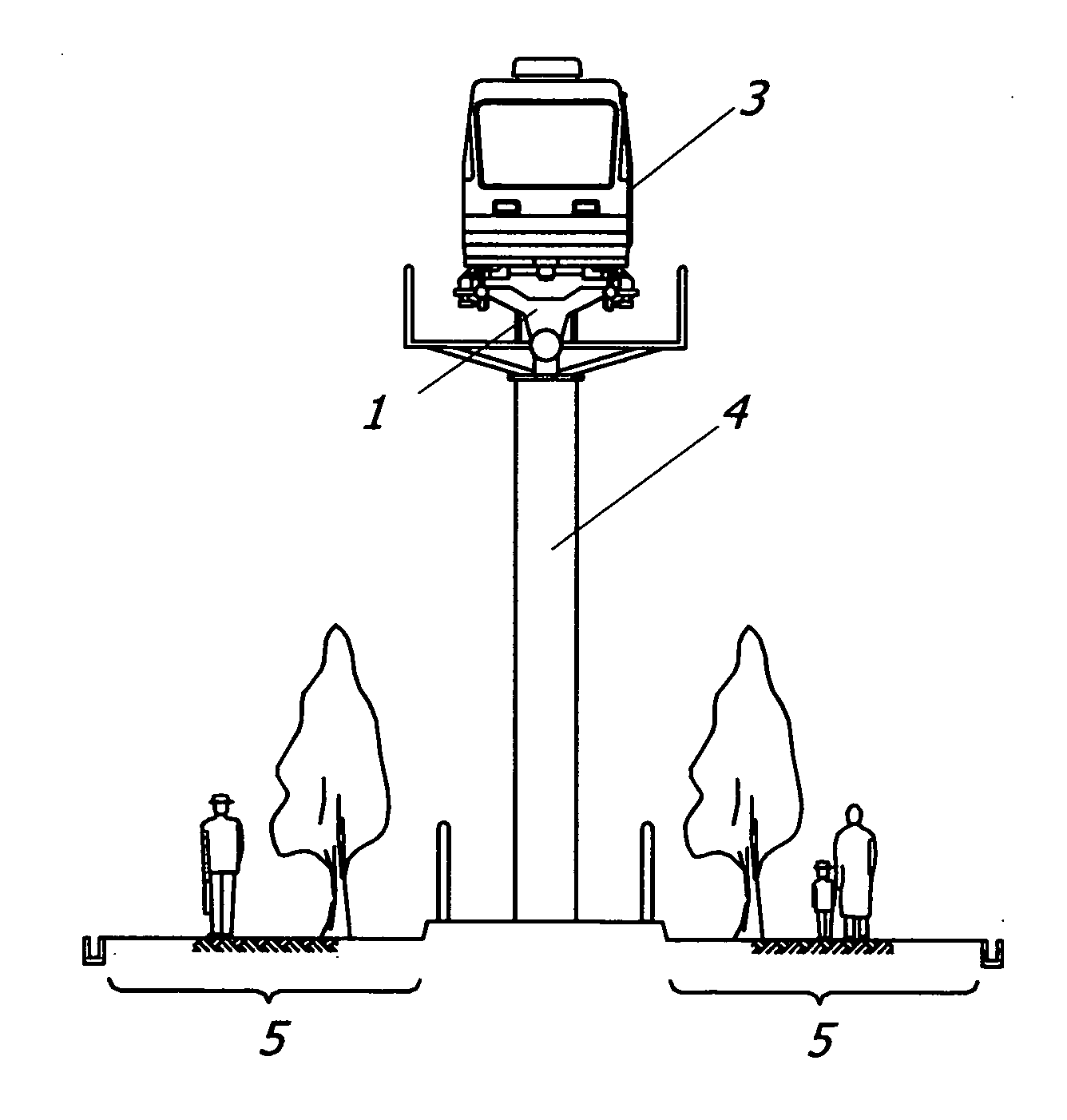
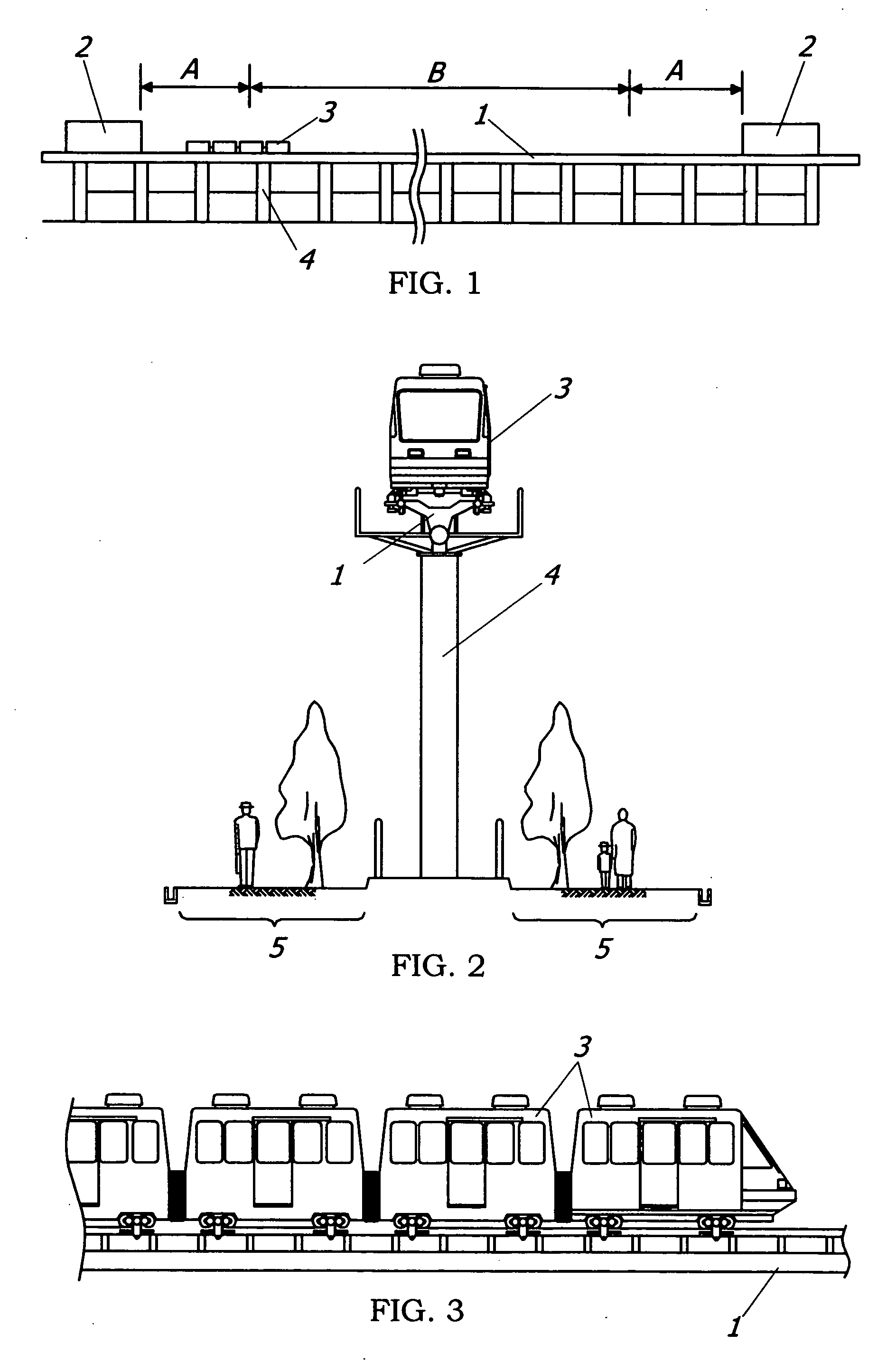
[0026] As a preferred embodiment of the transportation system of the present invention, a monorail system is explained. In this monorail system, as shown in FIGS. 1 to 3, a vehicle 3 is allowed to run between stations 2 on a rail 1 as a single track supported by bridge piers 4. In a first zone A, the vehicle 3 is accelerated from a stopped condition to a required speed by a propulsion force supplied from a propulsion supply unit, which is located from one of the stations toward the other station by a predetermined distance. In a second zone B, the vehicle 3 travels by use of a drive unit mounted thereon.

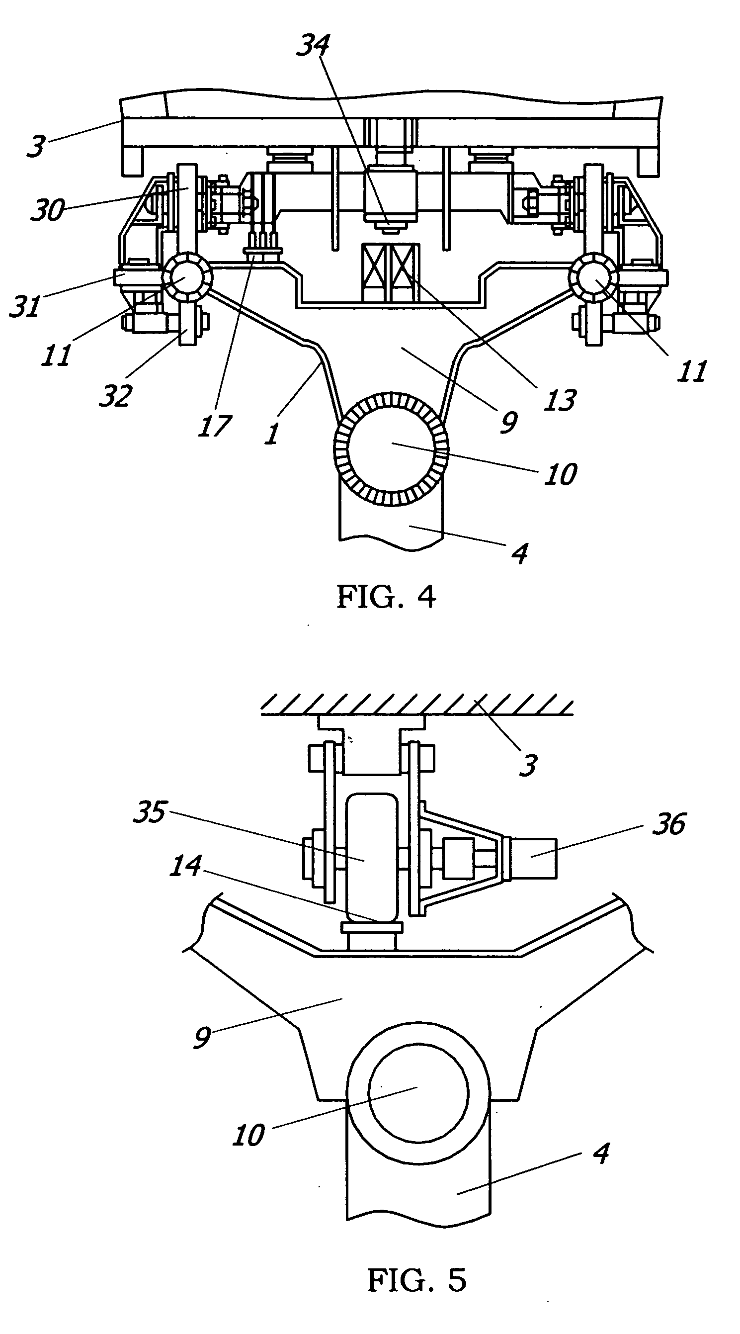
[0027] In the present embodiment, a liner-type accelerator is used as the propulsion supply unit disposed in the first zone A. That is, the rail 1 extends horizontally in the first zone A, and a fixed magnet 13 is disposed along the rail 1. The fixed magnet 13 gives the propulsion force to a movable magnet 34 mounted on the vehicle 3 to accelerate the vehicle 3, as shown in FIG. 4. ...

second embodiment

[0036] In the above embodiment, the monorail system having the first zone A, in which the linear-type accelerator is provided in the vicinity of the respective station 2, was explained. As shown in FIG. 8, the monorail system of the present embodiment is substantially the same as that of the first embodiment except that the first zone A using the linear-type accelerator is formed in the vicinity of one of the stations 20, and a third zone C using a coaster-type accelerator is formed in the vicinity of the other station 21 as the propulsion supplying unit other than the linear-type accelerator. Therefore, duplicate explanations are omitted.

[0037] As shown in FIG. 9, the coaster-type accelerator of this embodiment is mainly composed of an additional rail 100 formed at an uphill gradient in the vicinity of the station, and a lifting device (not shown) fixed at a top end of the additional rail. For example, the lifting device comprises a motor with reduction gears and a chain. Alternat...


PUM


Abstract

A transportation system is provided, in which a light-weight, small-sized vehicle can be used. This transportation system comprises a rail extending between stations, vehicle capable of running on the rail and carrying a drive unit, first zone for accelerating the vehicle from a stopped condition to a required speed by a propulsion force supplied from a propulsion supply unit provided from one of the stations toward the other station by a predetermined distance, and a second zone not having the propulsion supply unit, in which the vehicle accelerated in the first zone travels on the rail by the propulsion force supplied from the drive unit.

Description

TECHNICAL FIELD [0001] The present invention relates a transportation system for passengers or cargos, and particularly a monorail system where a small-sized, light-weighted vehicle can be used. BACKGROUND ART [0002] In the past, monorail has been widely used as a transportation system connecting between two sites spaced by a short to middle distance (for example, 5 to 20 km) such as between residential and industrial districts or between downtown and airport. In the monorail, since a rail is supported by bridge piers constructed on the ground at a required interval, there are advantages that the degree of freedom of design of transportation route is high, and the construction cost can be saved due to a reduced land area for construction, as compared with the case of laying rails for a regular railway. [0003] On the other hand, a large drive unit is usually needed to accelerate a vehicle from a stopped condition to a required speed. When such a large drive unit is mounted in the veh...

Claims


Application Information

Patent Timeline
Patent Type & Authority Applications(United States)
IPC IPC(8): B61K1/00A63G21/04A63G7/00B61B1/00B61B13/06B61B13/08B61B13/12
CPCA63G7/00Y02T30/30B61B13/12B61B1/00Y02T30/00A63G21/04B60L13/006B60N2/20B61B5/00B61B13/04
Inventor YAMADA, SABURO
Owner SENYO INDS
Why Eureka
Try Eureka