
Apparatus for drying substrate and method thereof

a technology for drying substrates and semiconductors, applied in liquid handling, packaging goods types, transportation and packaging, etc., can solve the problems of difficult to completely remove minute water drops that remain on the wafer, contamination in the processing tub, and the above-described problem becomes more severe, so as to reduce the distance between the substrate and the second nozzl

Inactive Publication Date: 2006-03-02
SAMSUNG ELECTRONICS CO LTD
View PDF2 Cites 13 Cited by
  • Summary
  • Abstract
  • Description
  • Claims
  • Application Information

AI Technical Summary

Benefits of technology

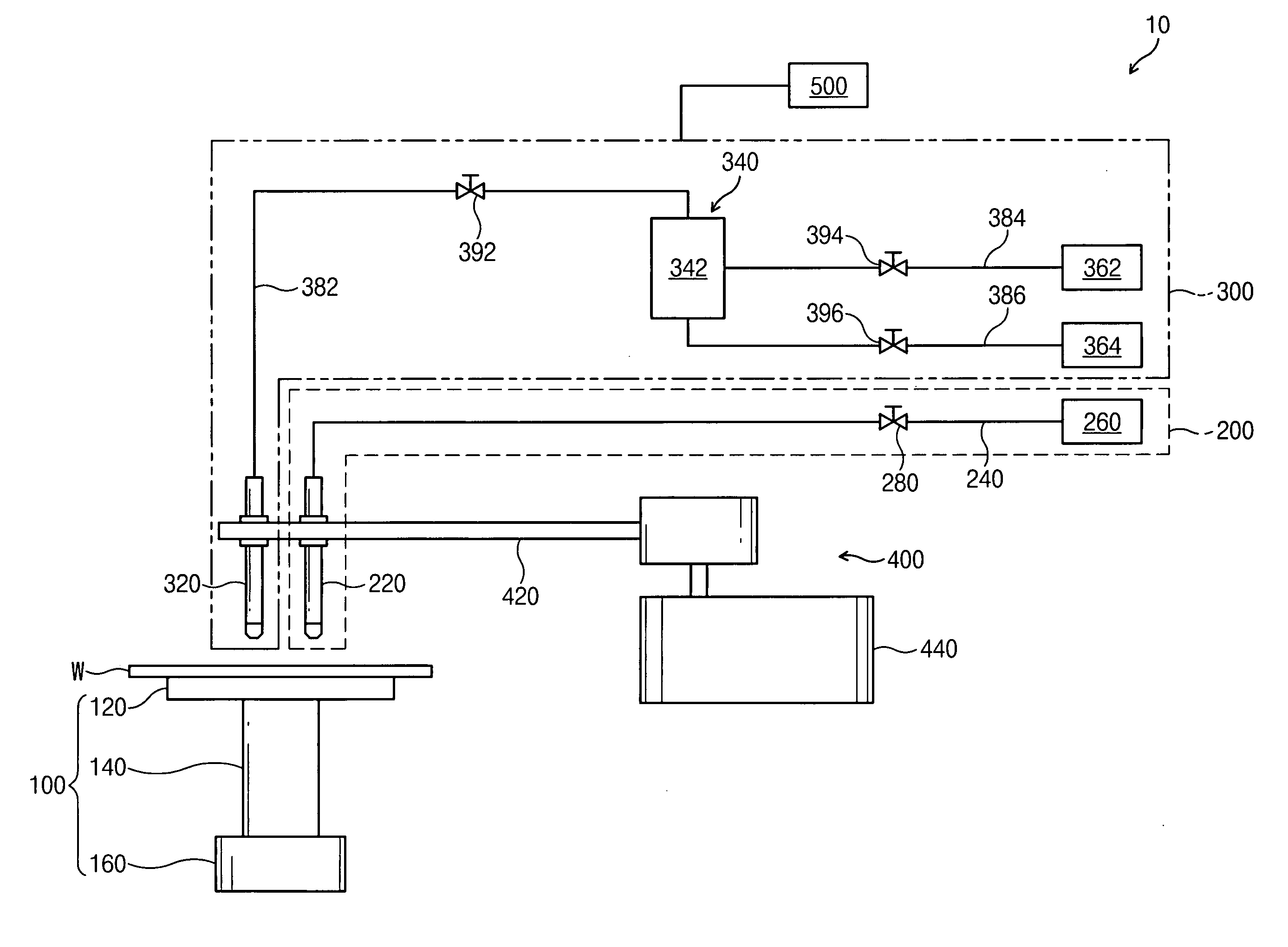
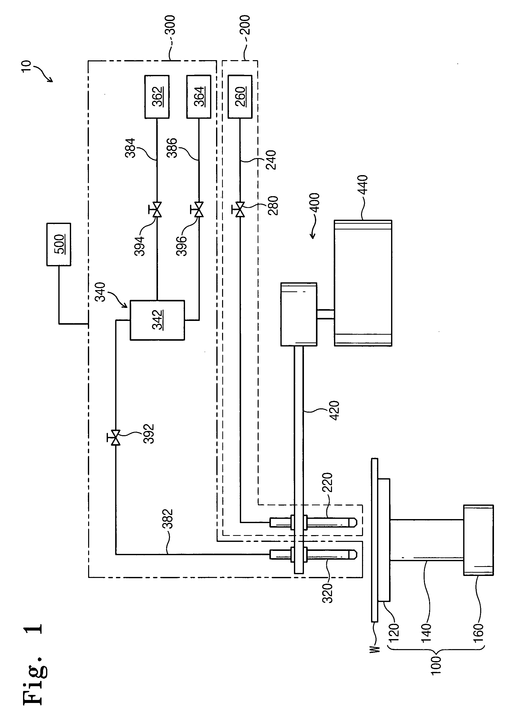
[0007] An embodiment of the present invention provides a drying apparatus that comprises a rotational supporting portion on which a substrate is placed. A first supplying portion and a second supplying portion are provided on the supporting portion. The first supplying portion has a first nozzle for spraying first liquid to the substrate that is placed on the supporting portion. The second supplying portion has a second nozzle for spraying second liquid to the substrate that is placed on the supporting portion. For example, the first liquid is de-ionized water and the second liquid is alcohol vapor such as isopropyl alcohol. There is provided a controlling portion for controlling the second supporting portion by gradually increasing the amount of the second liquid reaching the substrate that is placed on the supporting portion.
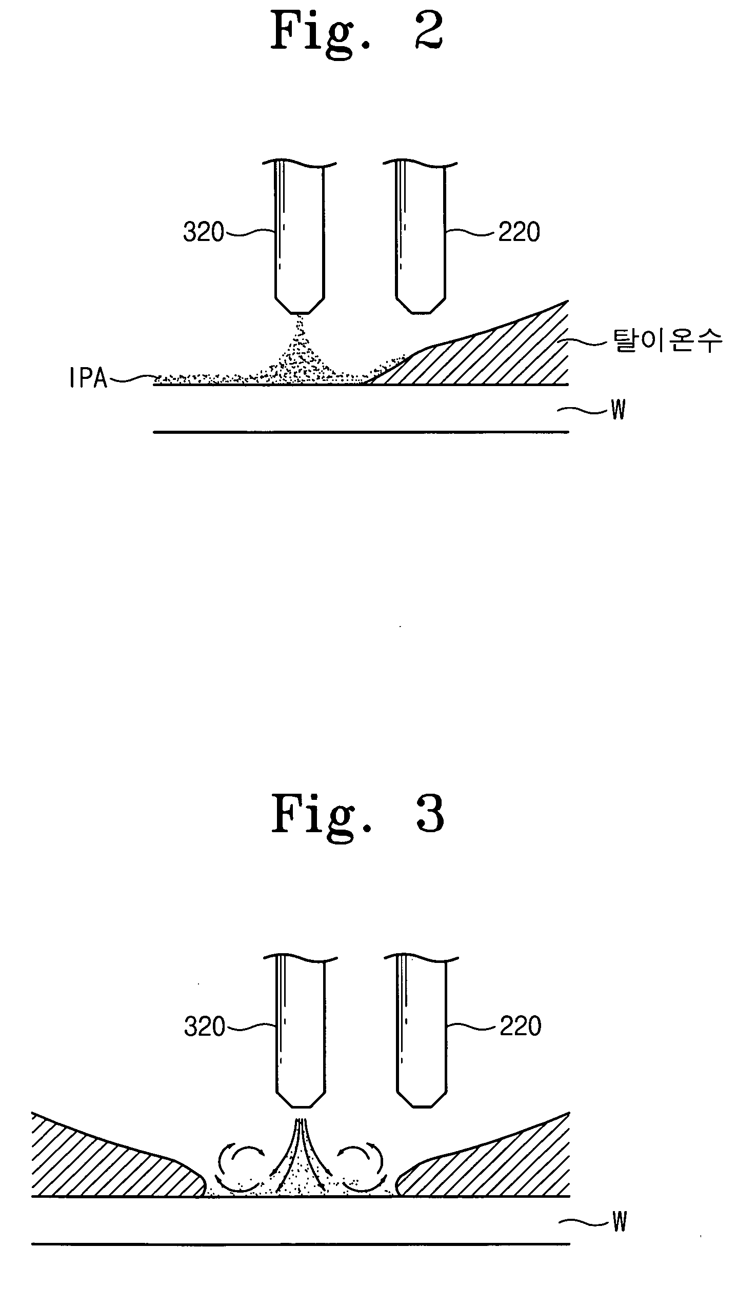
[0016] According to another embodiment, the amount of the second liquid is controlled by moving the second nozzle downward such that the distance between the substrate and the second nozzle is gradually reduced.

Problems solved by technology

However, as the integrated circuit becomes increasingly complicated, it is difficult to completely remove minute water drops that remain on a wafer resulting from the centrifugal force of the spin dryer because a large number of water marks is generated on the wafer after the drying process.
Therefore, when the drying process is performed on a group of wafers, contaminants reside in the processing tub.
But, the contaminants may contaminate a subsequent group of wafers on which the drying process is performed in the processing tub.
In particular, when the entire liquid chemical processing process, rinsing process, and drying process are performed in one processing tub, the above-described problem becomes more severe.

Method used


Image

  • Apparatus for drying substrate and method thereof
  • Apparatus for drying substrate and method thereof
  • Apparatus for drying substrate and method thereof

Examples


Embodiment Construction

[0029] Hereinafter, embodiments of the present invention will be described in more detail with reference to FIGS. 1 to 11.

[0030] Preferred embodiments of the present invention will be described below in more detail with reference to the accompanying drawings. The present invention may, however, be embodied in different forms and should not be constructed as limited to the embodiments set forth herein. Rather, these embodiments are provided so that this disclosure will be thorough and complete, and will fully convey the scope of the invention to those skilled in the art. In the drawings, the thickness of layers and regions are exaggerated for clarity.

[0031]FIG. 1 schematically illustrates a drying apparatus according to a preferred embodiment of the present invention. Referring to FIG. 1, a drying apparatus 10 includes a supporting portion 100, a first supplying portion 200, a second supplying portion 300, a horizontally moving portion 400, and a controlling portion 500. A semicond...


PUM

PropertyMeasurementUnit
surface tensionaaaaaaaaaa
timeaaaaaaaaaa
distanceaaaaaaaaaa

Abstract

An apparatus for drying a substrate using the Marangoni effect is disclosed. The apparatus includes a rotatable supporting portion on which a substrate is placed. A first nozzle for supplying de-ionized water and a second nozzle for supplying isopropyl alcohol vapor are provided on the supporting portion. When the isopropyl alcohol vapor is supplied to the center of the substrate at the initial stage, the amount of alcohol that reaches the substrate is controlled by a controlling portion such that the amount of the second liquid gradually increases.

Description

CROSS-REFERENCE TO RELATED APPLICATIONS [0001] This patent application claims priority under 35 U.S.C. § 119 to Korean Patent Application 2004-47155 filed on Jun. 23, 2004, the entire contents of which are hereby incorporated by reference. BACKGROUND OF THE INVENTION [0002] The present invention relates to an apparatus for fabricating a semiconductor device and a method thereof and more particularly, to an apparatus for drying a semiconductor wafer using the Marangoni effect and a method thereof. [0003] A process step for fabricating an integrated circuit on a semiconductor wafer requires cleaning the semiconductor wafer to remove residual chemicals, small particles, and contaminants generated during various fabricating processes. In particular, when a highly integrated circuit is fabricated, special attention is paid to the process of cleaning minute contaminants attached to the surface of the semiconductor wafer. [0004] The process of cleaning the semiconductor wafer is divided in...

Claims


Application Information

Patent Timeline
Patent Type & Authority Applications(United States)
IPC IPC(8): B65B1/04H01L21/00H01L21/304
CPCH01L21/67051H01L21/67034H01L21/304
Inventor KIM, SANG-YONGHONG, CHANG-KICHOI, SANG-JUNSHIM, WOO-GWAN
Owner SAMSUNG ELECTRONICS CO LTD
Learn More