Fixed-frequency current mode converter and control method thereof

a converter and current mode technology, applied in the direction of power conversion systems, dc-dc conversion, instruments, etc., can solve the problems of complex control of fixed-frequency operation, complexity and cost of the system, and achieve the effect of fast response to load transients

Inactive Publication Date: 2006-03-02
RICHTEK TECH
View PDF10 Cites 113 Cited by
  • Summary
  • Abstract
  • Description
  • Claims
  • Application Information

AI Technical Summary

Benefits of technology

[0008] In a single-phase fixed-frequency current mode converter comprising a power stage to produce an inductor current and an output voltage, according to the present invention, a current sense circuit senses the inductor current to generate a first current sense signal and a second current sense signal, a reference voltage generator generates a reference voltage varied with the inductor current by using the first current sense signal, an error amplifier generates an error signal from the difference between the output voltage and reference voltage to supply to a comparator, a ramp generator generates a ramp signal varied with the inductor current by using the second current sense signal, the comparator compares the error signal with the ramp signal to generate a comparison signal, a clock generator generates a fixed-frequency clock, and a pulse width modulation (PWM) generator generates a PWM signal in response to the clock and comparison signal for driving the power stage. The clock determines the rising edge of the PWM signal, and the comparison signal determines the falling edge of the PWM signal. In an embodiment, the current sense circuit comprises a transconductive amplifier to sense the inductor current to produce a third current sense signal, a sample and hold circuit to sample and hold the third current sense signal to produce the first current sense signal, and another sample circuit to sample the third current sense signal to produce the second current sense signal. To achieve faster response to load transient, a second reference voltage generator generates a second reference voltage varied with the inductor current, a second comparator compares the error signal with the second reference voltage for generating a second comparison signal, and once the error signal is lower than the second reference voltage, the second comparison signal will force the fixed-frequency clock generator to reset the fixed-frequency clock.

Problems solved by technology

Unfortunately, the control for such operation with varying frequency is much more complicated than that of fixed-frequency operation.
As a result, the complexity and cost of the system increase.

Method used


Image

  • Fixed-frequency current mode converter and control method thereof
  • Fixed-frequency current mode converter and control method thereof
  • Fixed-frequency current mode converter and control method thereof

Examples


Embodiment Construction

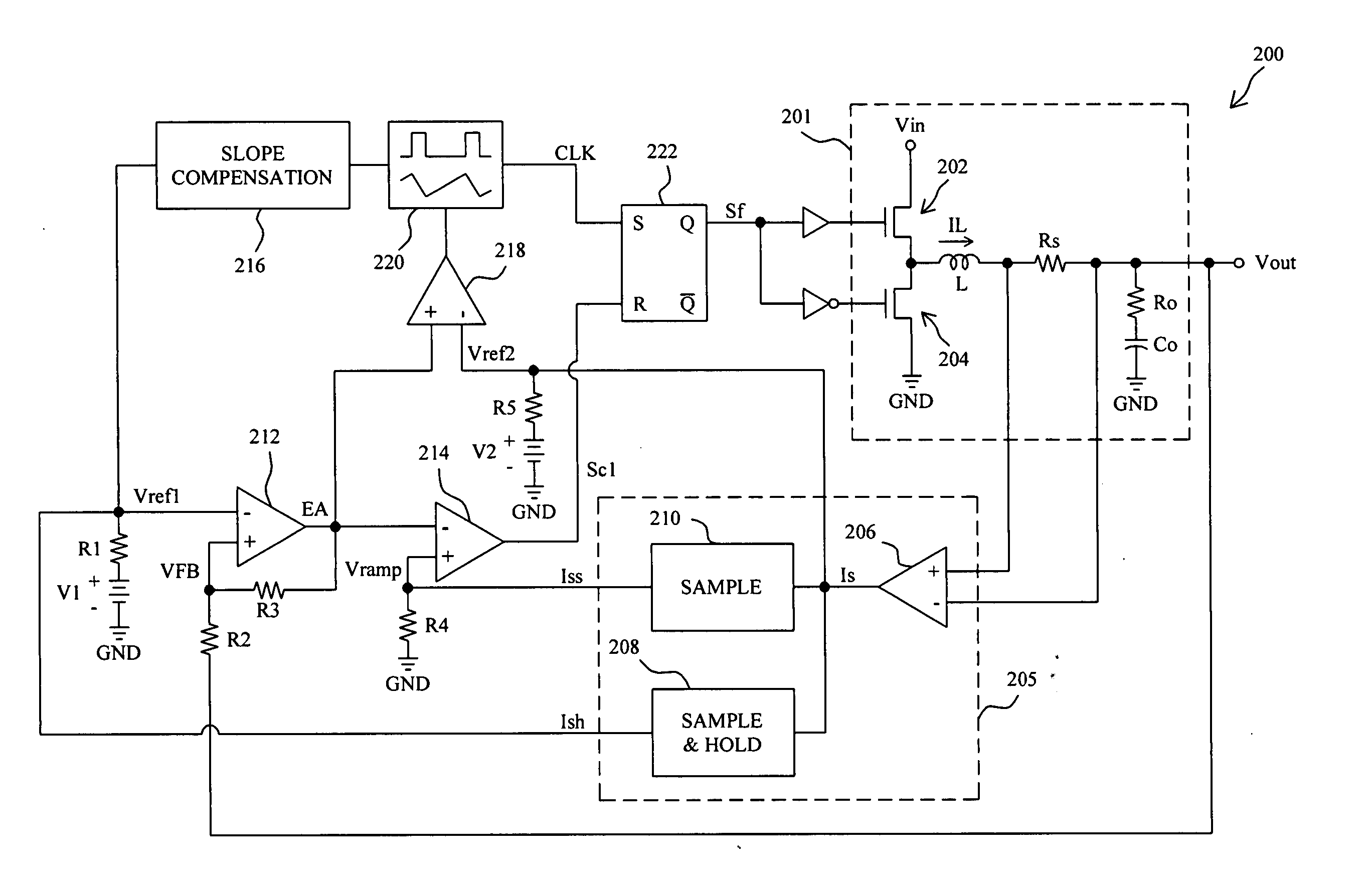
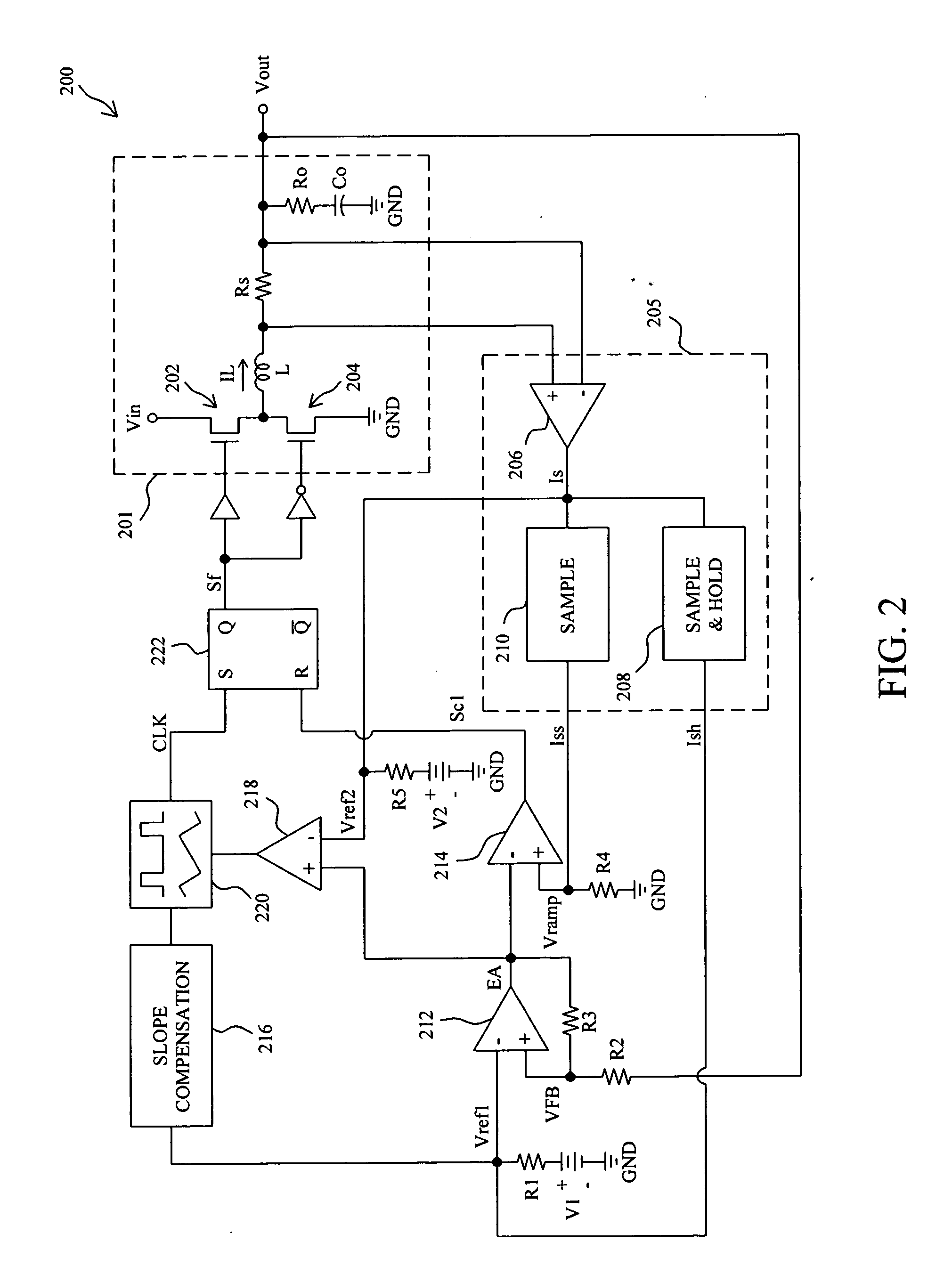
[0018]FIG. 2 shows a single-phase fixed-frequency current mode converter 200, in which power stage 201 includes a high side transistor 202 and a low side transistor 204 coupled in series between input voltage Vin and ground GND to be alternatively switched to produce an inductor current IL flowing through an inductor L to charge an output capacitor Co to produce output voltage Vout, current sense circuit 205 includes a transconductive amplifier 206 having its two inputs coupled to the two ends of a sense resistor Rs coupled in series to the inductor L to sense the inductor current IL to generate a current sense signal Is, sample and hold circuit 208 samples and holds the current sense signal Is to generate a current sense signal Ish, sample circuit 210 samples the current sense signal Is to generate a current sense signal Iss, resistor R1 and voltage source V1 constitute a reference voltage generator to generate a reference voltage Vref1 varied with the inductor current IL by using ...


PUM


Abstract

A fixed-frequency current mode converter comprises a power stage to produce an inductor current and an output voltage, an error amplifier to generate an error signal from the difference between the output voltage and a reference voltage varied with the inductor current, a comparator to compare the error signal with a ramp signal varied with the inductor current to generate a comparison signal, and a PWM generator to generate a PWM signal in response to a fixed-frequency clock and the comparison signal to drive the power stage. A second comparator is further comprised to compare the error signal with a second reference voltage varied with the inductor current, and generates a second comparison signal to reset the clock when the error signal is lower than the second reference voltage.

Description

FIELD OF THE INVENTION [0001] The present invention is related generally to a current mode converter and more particularly to a fixed-frequency current mode converter. BACKGROUND OF THE INVENTION [0002] In a current mode converter, typically, the output voltage is generated by alternatively switching a pair of high side and low side switches coupled between an input voltage and ground to produce an output current to charge an output capacitor. To reduce the influence to load transient resulted from the equivalent series resistance (ESR) of the output capacitor, voltage droop function is generally employed. To illustrate the voltage droop tuning, FIG. 1 schematically shows the waveforms of the output voltages of a current mode converter with and without voltage droop function in a load transient, in which waveform 100 represents the output voltage of a current mode converter without voltage droop function in a load transient, and waveform 102 represents the output voltage of a curren...

Claims


Application Information

Patent Timeline
Patent Type & Authority Applications(United States)
IPC IPC(8): G05F1/656
CPCH02M3/1584H02M3/158
Inventor HUANG, KENTTAI, LIANG-PIN
Owner RICHTEK TECH
Why Eureka
Try Eureka