
Bias-feeding device

a bias-feeding and device technology, applied in the direction of resistance/reactance/impedence, measurement devices, instruments, etc., can solve the problems of difficult suppression of oscillation, frequent induced unsatisfactory oscillation, and inability to suppress oscillation, etc., to achieve excellent versatility, suppress oscillation, and high precision

Inactive Publication Date: 2006-03-02
TDK CORPARATION
View PDF11 Cites 0 Cited by
  • Summary
  • Abstract
  • Description
  • Claims
  • Application Information

AI Technical Summary

Benefits of technology

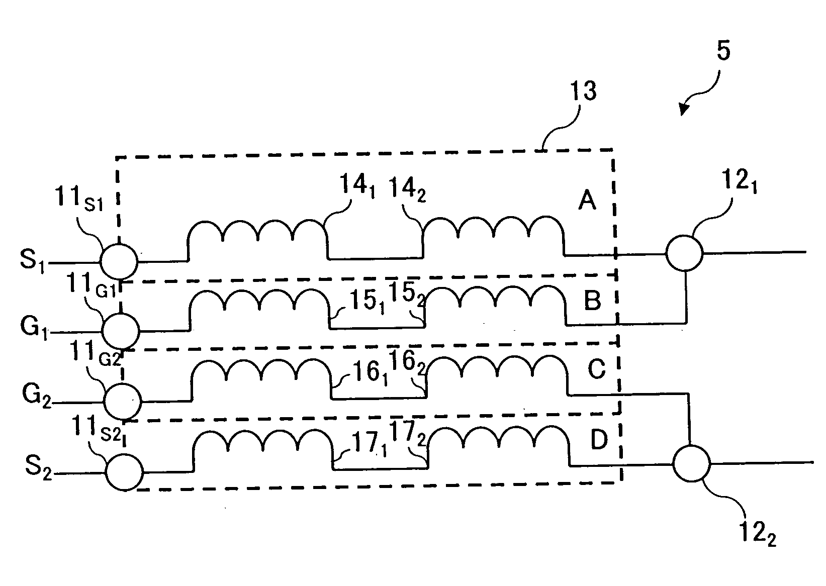
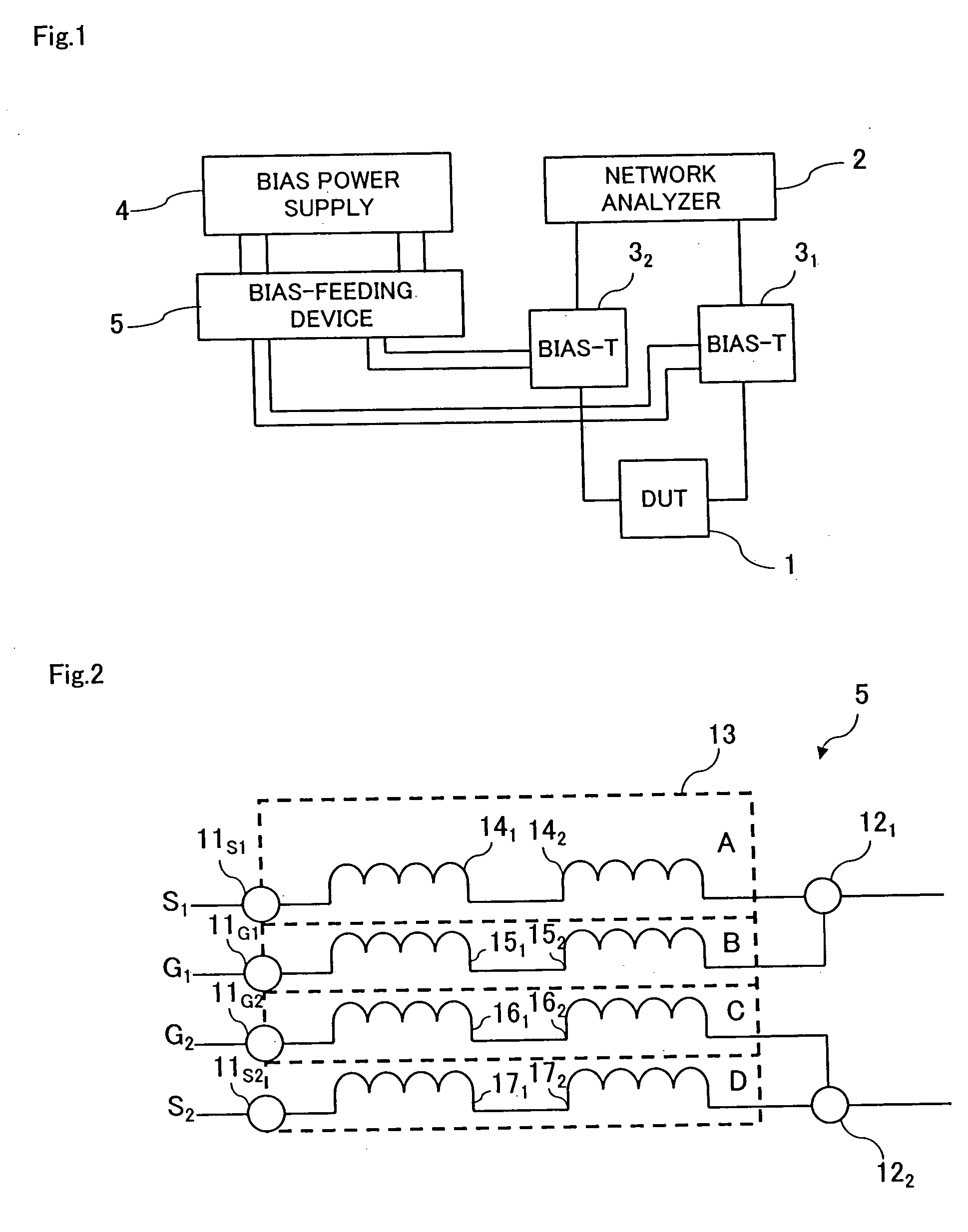
[0016] In the bias-feeding device according to the present invention, since the first signal line for feeding a bias voltage and the second signal line for feeding a reference potential are shielded from each other, it is possible to suppress as much as possible the connection between the first and second signal lines. In the bias-feeding device according to the present invention, furthermore, since a reactive element having such a closed magnetic path structure as inducing very small leakage of a magnetic flux is inserted into each of the first and second signal lines, both the first and second signal lines can be configured to exhibit high impedance at high frequencies and no loss from a viewpoint of direct current while configured not to be connected directly to the second signal line without connecting to each other the signal lines on the input and output sides of a physical object to be measured in the vicinity of the physical object. By using the bias-feeding device of the present invention for at least one of the input and output sides of the physical object, it is possible to infallibly prevent the electric coupling between the input and output sides of the physical object and to infallibly suppress the induction of oscillation.
[0018] The bias-feeding device according to the present invention is equipped with a first shielded casing in which the first signal line is accommodated as inserted and a shielded second casing in which the second signal line is accommodated as inserted. As a result, the bias-feeding device according to the present invention can infallibly suppress the connection between the first and second signal lines.
[0020] Moreover, the first output terminal can be configured as a central terminal for connecting a coaxial cable, and the second output terminal can be configured as an outer terminal for connecting the coaxial cable. Thus, the bias-feeding device according to the present invention can be connected via the coaxial cable to a physical object to be measured and is therefore excellent in versatility.
[0021] It is to be noted that as the physical object to be measured, an active element can be applied. The bias-feeding device according to the present invention is advantageously used for measurement of the impedance and / or other parameters of the active element. That is to say, with a measurement system to which the bias-feeding device of the present invention is applied, undesirable oscillation can infallibly be suppressed, with the result that the impedance and other parameters of the active element can be measured with high precision and that breakage of the active element and measurement equipment resulted from the oscillation can be prevented from occurring.
[0022] According to the present invention, therefore, the electric coupling through first and second signal lines between the input and output sides of a physical object to be measured can infallibly be prevented to infallibly suppress oscillation.

Problems solved by technology

In this kind of measurement, however, since the frequency to be measured is a wide band, any frequency within a measurement range is in agreement with oscillation conditions and undesired oscillations are frequently induced.
Particularly where a recently developed compound material semiconductor element is used as a DUT, since the frequency in use extends up to a millimeter waveband to make the measurement range extremely wide band, it becomes difficult to suppress oscillation.
The DUT, however, undesirably has a frequency selection property since using the reactive element comprising an ordinary coil or the matching network by these methods, so that those methods is in inapplicable at all to measure uniformly over a wide band, which is problematic.
Particularly, in the case of the coil having a wire wound around a bobbin, since the reactive element has a capacitance between the wound wire parts and exhibits characteristics like those of a capacitor at frequency bands exceeding its self-resonant frequency point, thereby causing malfunctions.
Consequently, oscillation cannot be suppressed.
With the technique disclosed in JP-A 2000-304815, since a shield is merely provided between the power source and the DUT, it is also impossible to sufficiently suppress the electric coupling between the input side and the output side of the DUT.

Method used


Image

  • Bias-feeding device
  • Bias-feeding device
  • Bias-feeding device

Examples


Embodiment Construction

[0027] The present invention will be described hereinafter with reference to an embodiment thereof shown in the accompanying drawings.

[0028] In this embodiment, an active element including semiconductor elements such, e.g., as transistors etc. or a device under test (DUT) such as, e.g., amplifiers using the active element, is defined as a physical object to be measured. With a measurement system in which a bias signal is fed to the physical object to measure the impedance and / or other parameters of the physical object, a bias-feeding device of the present invention is provided between a power source and the physical object. In particular, this bias-feeding device can infallibly prevent the electric coupling between input and output sides of the physical object through a signal line for feeding a bias voltage or a ground line for feeding a ground potential defined as a reference potential and can infallibly suppress induction of oscillation over a wide band.

[0029] Specifically, the...


PUM


Abstract

A bias-feeding device for feeding a bias signal to a physical object to be measured includes a first input terminal for inputting thereto a bias voltage, a second input terminal for inputting thereto a reference potential, a first output terminal for outputting the bias voltage to the physical object, a second output terminal for outputting the reference potential to the physical object, a first signal line for connecting the first input terminal and the first output terminal, a second signal line for connecting the second input terminal and the second output terminal, shielded from the first signal line, a first reactive element of a closed magnetic path structure inserted into the first signal line and a second reactive element of a closed magnetic path structure inserted into the second signal line.

Description

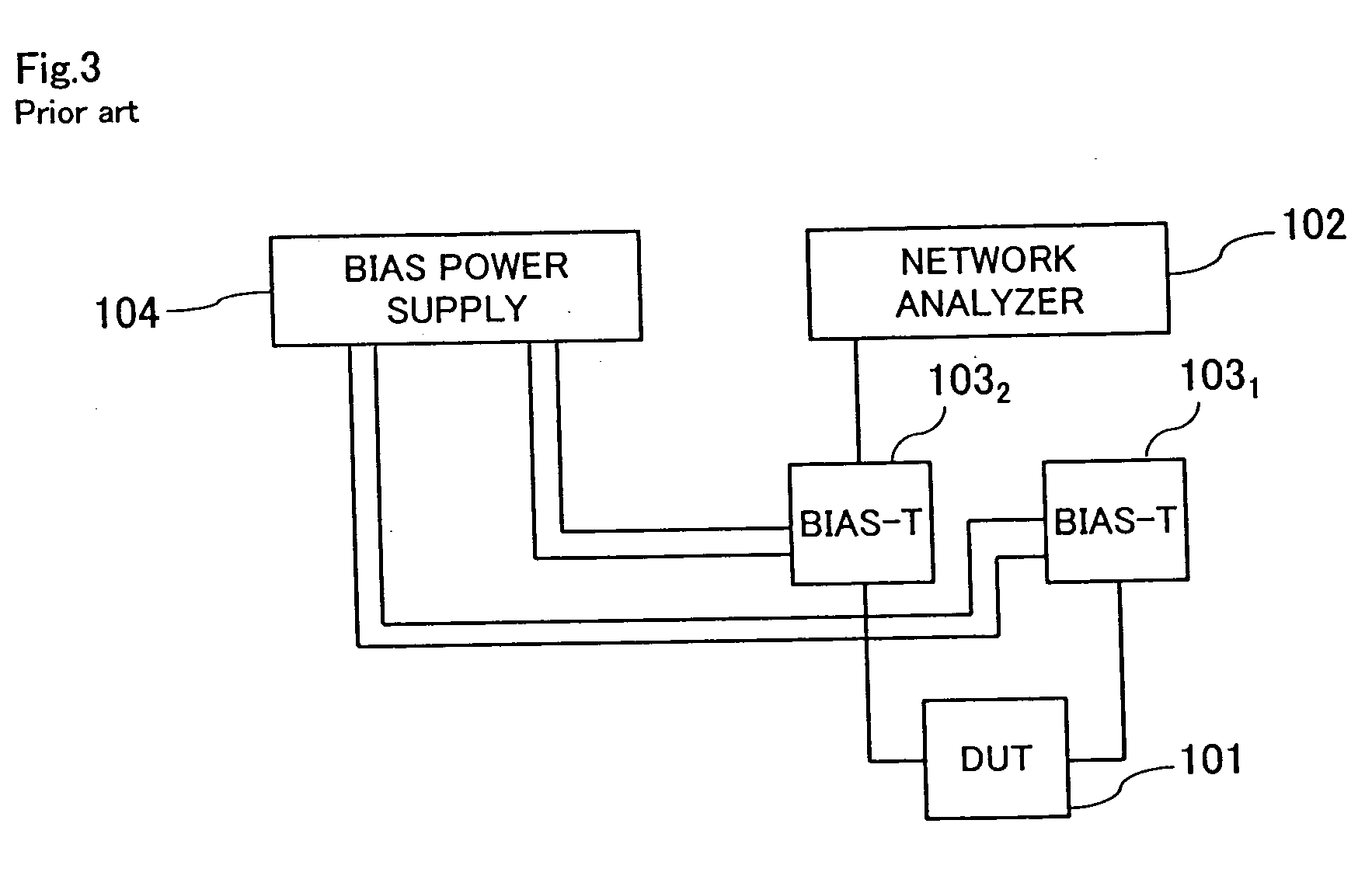
BACKGROUND OF THE INVENTION [0001] 1. Field of the invention [0002] The present invention relates to a bias-feeding device for feeding a bias signal to a physical object to be measured. [0003] 2. Description of the Prior Art [0004] Conventionally, a bias signal has been fed to a device under test (DUT) such as an active element including semiconductor elements or the like, for example, transistors etc., to measure the impedance and other parameters of the DUT. A measurement system of this kind comprises, as shown in FIG. 3, for example, a DUT 101, a network analyzer 102 for measuring the impedance and other parameters of the DUT 101, bias-T coaxial adapters 1031, 1032 for superimposing bias voltages in coaxial cables for measurement, via which the DUT 101 and the network analyzer 102 are connected to each other, and a bias power supply 104 for feeding a bias signal, which is connected to the bias-T coaxial adapters 1031, 1032. [0005] What greatest attention is to be paid to in this ...

Claims


Application Information

Patent Timeline
Patent Type & Authority Applications(United States)
IPC IPC(8): H03H7/00
CPCG01R27/32
Inventor IKEDA, HIROSHI
Owner TDK CORPARATION
Learn More