Piezoelectric actuator having piezoelectric layer and vibration plate with groove, liquid transporting apparatus, and method of manufacturing liquid transporting apparatus

a piezoelectric actuator and vibration plate technology, applied in the direction of electrical devices, piezoelectric/electrostrictive/magnetostrictive devices, printing, etc., can solve the problems of deteriorating discharge reliability, reducing yield, and high manufacturing cost of ink-jet heads, so as to reduce the number of grooves and reduce the cross talk. , the effect of easy formation of grooves

Active Publication Date: 2006-03-02
BROTHER KOGYO KK
View PDF6 Cites 37 Cited by
  • Summary
  • Abstract
  • Description
  • Claims
  • Application Information

AI Technical Summary

Benefits of technology

[0016] In the piezoelectric layer forming step in the method of manufacturing liquid transporting apparatus of the present invention, the piezoelectric layer may be formed by a chemical deposition method or an aerosol deposition method. When the piezoelectric layer is formed by the chemical deposition method or the aerosol deposition method, the piezoelectric layer on the surfaces of the grooves can be made easily thinner than the piezoelectric layer in an area other than the surfaces of the grooves.
[0017] In the groove forming step of the method of manufacturing liquid transporting apparatus of the present invention, the grooves may be formed to substantially surround the associated pressure chambers as viewed from the direction orthogonal to the flat surface. When the pressure chambers are respectively surrounded by the grooves, the deformation of the piezoelectric layer in the area overlapping with one of the pressure chambers is hardly propagated to an area overlapping with other pressure chamber, thereby reducing the cross talk assuredly.
[0018] In the groove forming step of the method of manufacturing liquid transporting apparatus of the present invention, one of the grooves may be common in an area between two adjacent pressure chambers. Thus, by forming the grooves commonly between the two pressure chambers, the number of grooves can be reduced. Further, since the thickness of one groove becomes greater, it is easy to form the grooves.
[0019] In the method of manufacturing liquid transporting apparatus of the present invention, the vibration plate may be formed of an electroconductive metallic material, and the method may further comprise an individual electrode forming step of forming a plurality of individual electrodes in an area of the piezoelectric layer, the area overlapping with the pressure chambers as viewed from a direction orthogonal to the flat surface, after the piezoelectric layer forming step. Thus, since the vibration plate is made of the metallic material, the grooves can be formed easily in the vibration plate by a method such as etching. Moreover, since the vibration plate is electroconductive, the vibration plate can be made to function as a common electrode

Problems solved by technology

However, if an attempt is made to form this groove by a mechanical process such as dicing, the manufacturing cost of the ink-jet head becomes very high.
However, if the groove is formed by a mechanical process on the piezoelectric element after baking, a chip or a crack ten

Method used


Image

  • Piezoelectric actuator having piezoelectric layer and vibration plate with groove, liquid transporting apparatus, and method of manufacturing liquid transporting apparatus
  • Piezoelectric actuator having piezoelectric layer and vibration plate with groove, liquid transporting apparatus, and method of manufacturing liquid transporting apparatus
  • Piezoelectric actuator having piezoelectric layer and vibration plate with groove, liquid transporting apparatus, and method of manufacturing liquid transporting apparatus

Examples


first embodiment

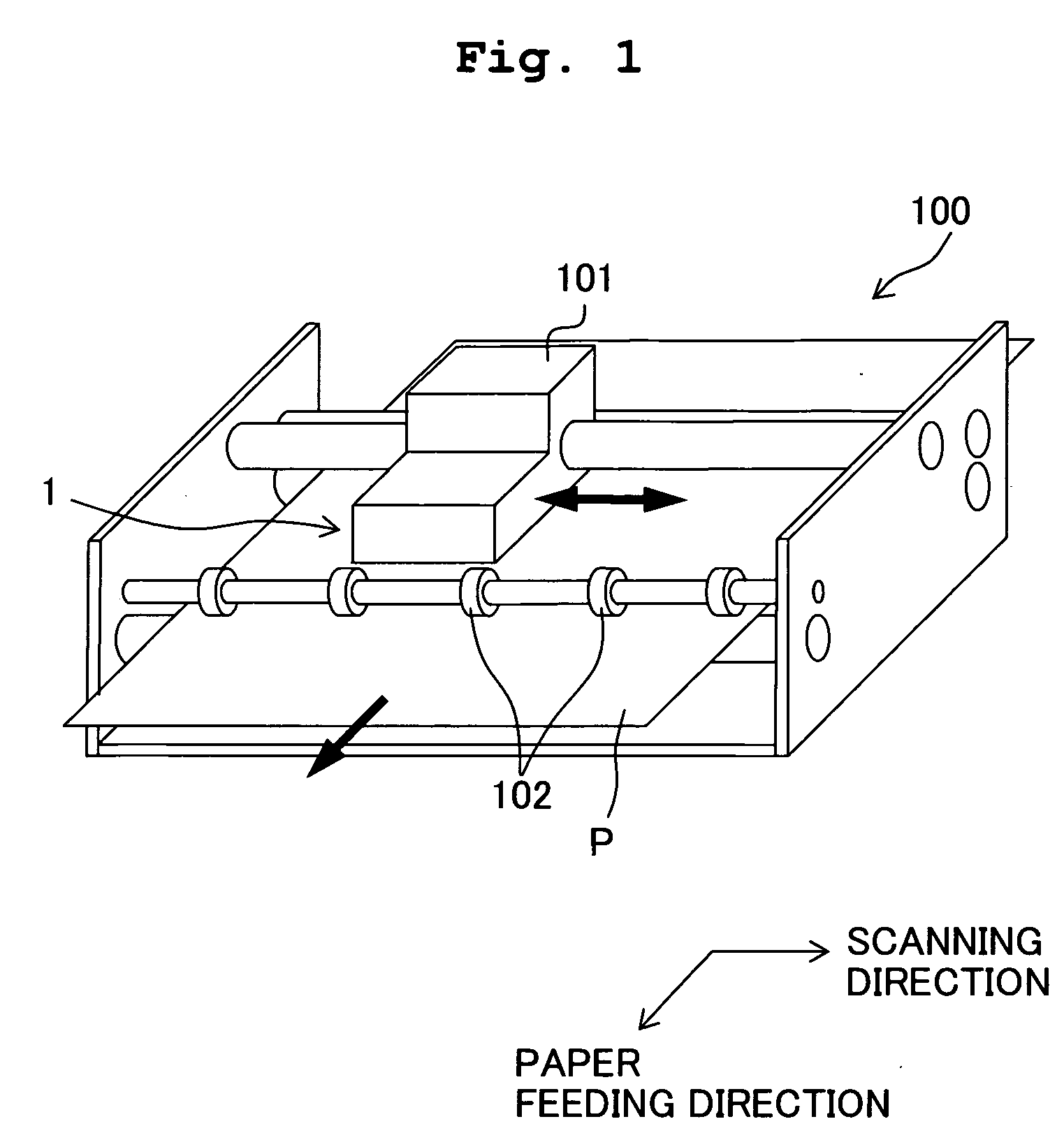
[0046] Embodiments of the present invention will be described below. A first embodiment is an example in which the present invention is applied to an ink-jet head which discharges ink on a recording paper as a liquid-jet apparatus. Firstly, an ink-jet printer 100 which includes an ink-jet head 1 will be described briefly. As shown in FIG. 1, the ink-jet printer 100 includes a carriage 101 which is movable in a left and right direction in the drawing (direction indicated by a two-pointed arrow), the ink-jet head 1 of serial type which is provided on the carriage 101 and discharges ink onto a recording paper P, and transporting rollers 102 which carry the recording paper P in a forward direction (direction indicated by a horizontal arrow) in FIG. 1. The ink-jet head 1 moves integrally with the carriage 101 in a left and right direction (scanning direction) and discharges ink onto the recording paper P from ejecting ports of nozzles 20 (refer FIGS. 2 to 5) formed in an ink-discharge su...

second embodiment

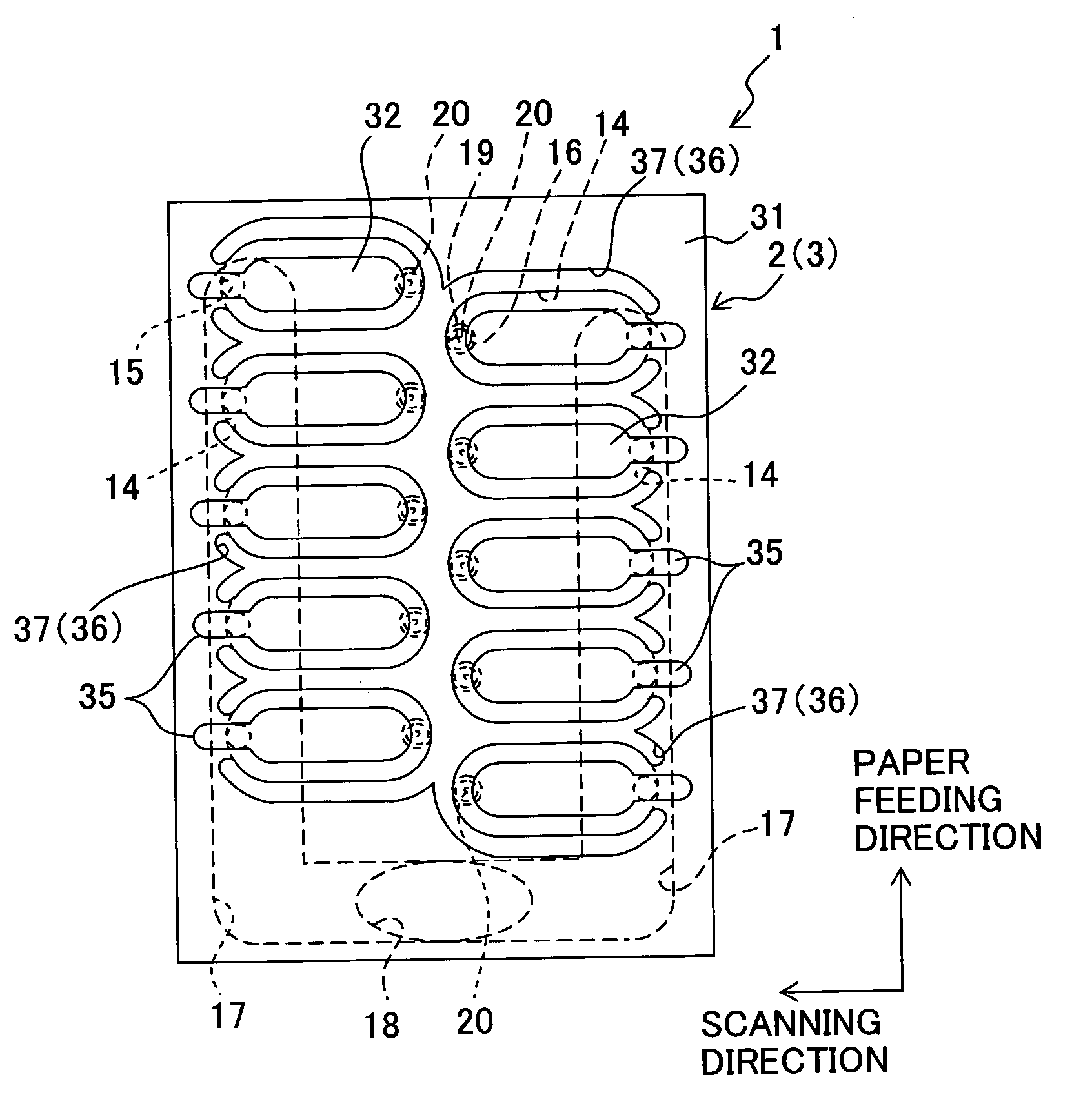
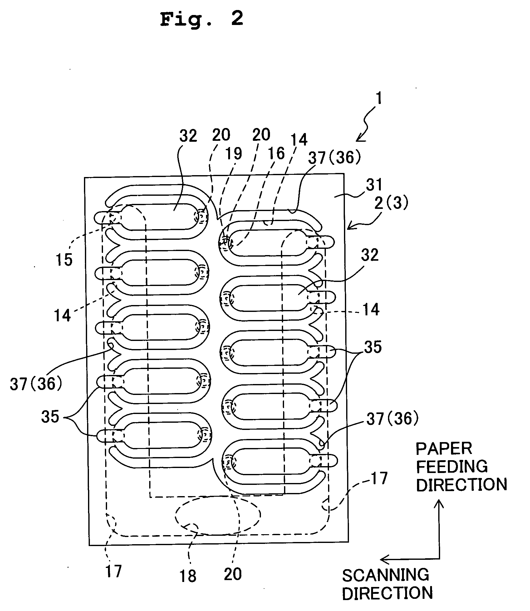
[0074] In the piezoelectric actuator of the ink-jet head in the first embodiment, the grooves are formed in the area of the vibration plate which does not overlap with the pressure chambers, but in a piezoelectric actuator of an ink-jet head in a second embodiment, the grooves are formed in the area of the vibration plate which overlaps with the pressure chambers 14. In a piezoelectric actuator 103 of the ink-jet head 101 in the second embodiment, a groove 136 formed in a vibration plate 130 is provided at a position which overlaps with a circumferential portion of each of the pressure chambers 14 as shown in FIGS. 13 to 15 (plan view in FIG. 13). Therefore, a groove 137 corresponding to each of the grooves 136 in the vibration plate 130 is formed in a piezoelectric layer 131 which is formed on the vibration plate 130. The groove 137 in the piezoelectric layer 131 is also provided at a position which overlaps with one of the pressure chambers 14, and in particular with a circumferen...

third embodiment

[0075] In a third embodiment also, an example of an ink-jet head which includes a piezoelectric actuator in which the groove in the vibration plate is formed in an area overlapping with each of the pressure chambers is described. Particularly, in a piezoelectric actuator 203 of this ink-jet head 201, a groove 236 formed in a vibration plate 230 is provided so that the groove 236 surrounds a central portion of each of the pressure chambers 14 as shown in FIGS. 16 to 18 (plan view in FIG. 16). In other words, the grooves are provided so as to divide the area on the vibration plate corresponding to the piezoelectric layer between the central portion and a peripheral portion. Therefore, a groove 237 corresponding to each of the grooves 236 in the vibration plate 230 is formed in a piezoelectric layer 231 which is formed on the vibration plate 230. Individual electrodes 134 are formed to circumvent the grooves 237 on the piezoelectric layer, leaving the grooves 37 uncovered. The grooves ...


PUM

PropertyMeasurementUnit
Thicknessaaaaaaaaaa
Pressureaaaaaaaaaa
Areaaaaaaaaaaa

Abstract

A method of manufacturing an ink-jet head according to the present invention includes a step of providing a vibration plate in which grooves associated with respective pressure chambers are formed on a surface of the vibration plate, and a piezoelectric layer forming step of forming a piezoelectric layer by depositing particles of a piezoelectric material on the surface of the vibration plate on an opposite side of a channel unit. Since grooves corresponding to the grooves in the vibration plate are formed also in the piezoelectric layer, it is possible to reduce a cross talk between operating sections of the piezoelectric layer. Further, chip and crack is hardly developed in the piezoelectric layer.

Description

BACKGROUND OF THE INVENTION [0001] 1. Field of the Invention [0002] The present invention relates to a piezoelectric actuator, a liquid transporting apparatus, and a method of manufacturing liquid transporting apparatus, and in particular to a piezoelectric actuator, a liquid transporting apparatus, and a method of manufacturing liquid transporting apparatus in which a cross talk between a plurality of operating sections is reduced. [0003] 2. Description of the Related Art [0004] An ink-jet head which discharges ink from a nozzle onto a recording paper is an example of a liquid transporting apparatus which discharges liquid onto an object subjected to discharge. This ink-jet head includes a channel unit which has an ink-discharge channel including a pressure chamber which communicates with the nozzle, and a piezoelectric actuator which causes an ink to be discharged from the nozzle by changing a volume of the pressure chamber. In this case, a general piezoelectric actuator includes ...

Claims


Application Information

Patent Timeline
IPC IPC(8): B41J2/045
CPCB41J2/14233B41J2/161B41J2/1623B41J2/1626Y10T29/49401B41J2/1646H01L41/0973Y10T29/42B41J2/1642H10N30/2047
Inventor SUGAHARA, HIROTO
Owner BROTHER KOGYO KK
Why Eureka
Try Eureka