Light-emitting diode and its manufacturing method

Inactive Publication Date: 2006-10-24
SHARP KK
View PDF15 Cites 11 Cited by
  • Summary
  • Abstract
  • Description
  • Claims
  • Application Information

AI Technical Summary

Benefits of technology

[0028]The manufacturing method of the light-emitting diode according to the present inve

Problems solved by technology

However, these LEDs have the following problems.
Specifically, the first type LED, although it is easy to make this LED thin, has a problem that the LED chip is proximal to the printed substrate where the chip should be mounted.
It also has another problem that so

Method used


Image

  • Light-emitting diode and its manufacturing method
  • Light-emitting diode and its manufacturing method
  • Light-emitting diode and its manufacturing method

Examples


Embodiment Construction

[0039]Explained hereinbelow is a preferred embodiment of a surface-mounted LED and its manufacturing method according to the present invention.

[0040]The present embodiment utilizes a blue LED chip or green LED chip of GaN group as one example of an LED chip.

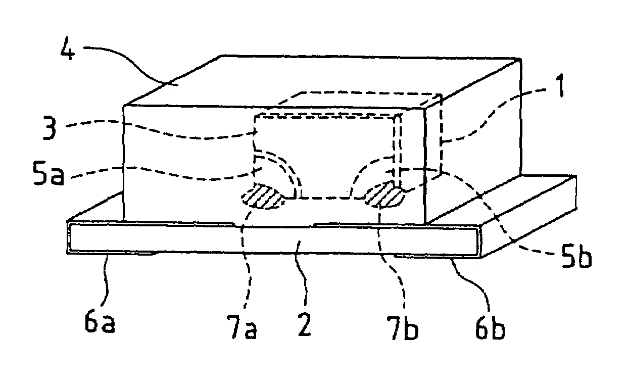
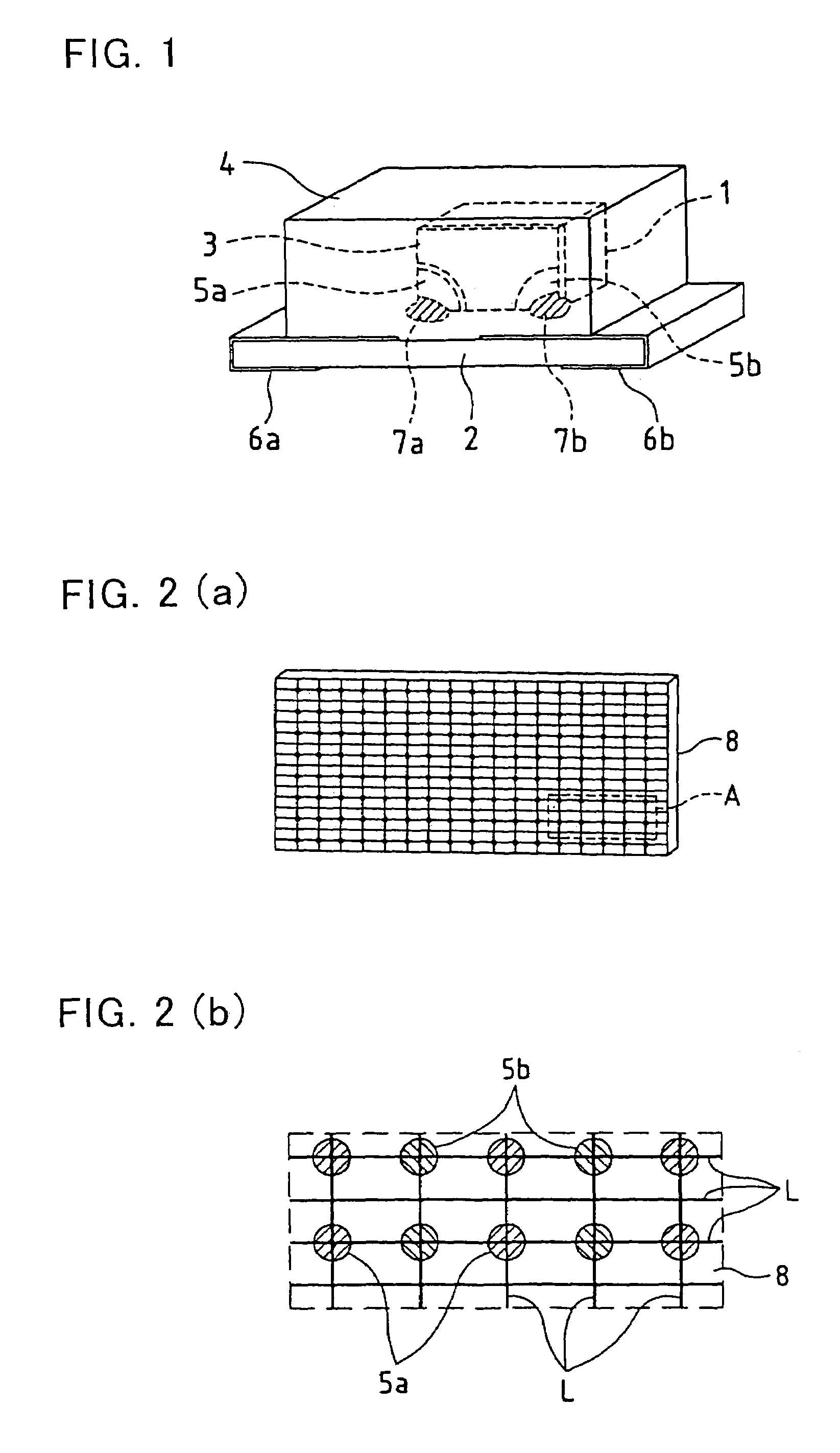
[0041]FIG. 1 is a perspective view showing one embodiment of a surface-mounted LED according to the present invention.

[0042]Shown in this embodiment is a substrate type side-emitting surface-mounted LED wherein an LED chip 1 is mounted on a substrate 2 such that a PN junction of the LED chip 1 is perpendicular to the substrate surface.

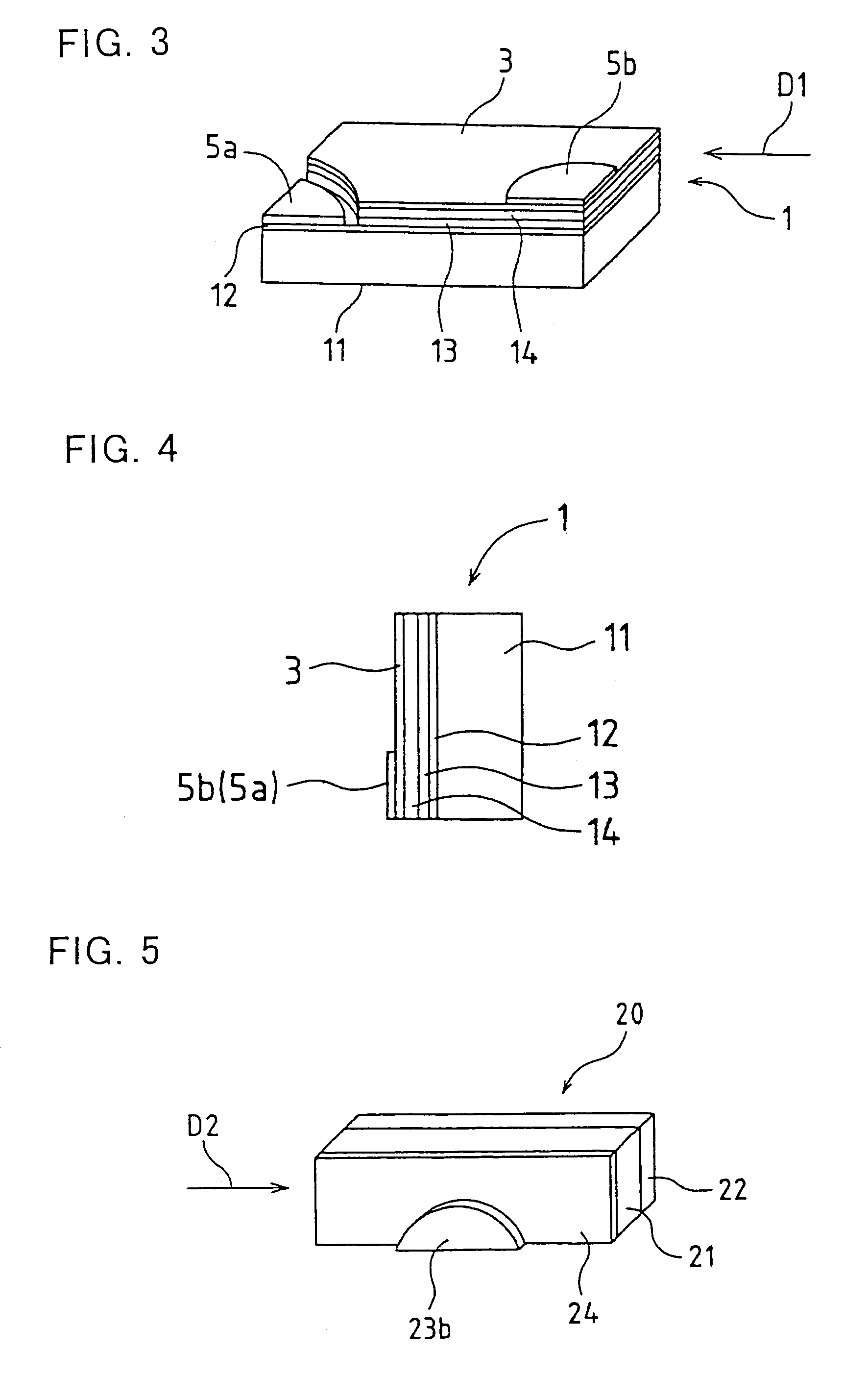
[0043]A light reflecting layer is provided at one surface of the LED chip. The present embodiment utilizes a reflection mirror 3, serving as the light reflecting layer, provided on a surface parallel to the PN junction surface.

[0044]The surface of the LED chip 1 is covered with a mold resin portion 4 (for example, made of epoxy resin as a translucent resin). Two chip electrodes 5a and 5b are electri...


PUM


Abstract

The present invention provides a surface-mounted LED that is easy to be made thin and having high reliability, as well as provides its manufacturing method.
Specifically, the present invention provides a light-emitting diode having a light-emitting diode chip mounted on a surface of a printed substrate, this light-emitting diode chip comprising a substrate; a semiconductor layer laminated on the substrate and comprising an N-type semiconductor layer and a P-type semiconductor layer, wherein its PN junction surface is perpendicular to the surface of the printed substrate and a portion in the vicinity of the PN junction surface is rendered to be a light-emitting portion; a pair of electrodes that applies voltage to the semiconductor layer; and a light reflecting layer formed on the front surface or back surface of the light-emitting chip or in the chip so as to be approximately parallel to the PN junction surface, this light reflecting layer reflecting light emitted from the light-emitting portion.

Description

CROSS-REFERENCE TO RELATED APPLICATIONS[0001]This application claims priority to Japanese Patent Application Number 2001-050558 filed Feb. 26, 2001, and Japanese Patent Application Number 2002-41913 filed Feb. 19, 2002, the contents of which are incorporated herein by reference in their entireties.BACKGROUND OF THE INVENTION[0002]1. Field of the Invention[0003]The present invention relates to a light-emitting diode and its manufacturing method, and more particularly to a substrate type surface-mounted light-emitting diode (hereinafter simply abbreviated to LED) with a side emission and its manufacturing method, this surface-mounted LED including an LED chip mounted on a printed substrate such that the PN junction surface of the chip is perpendicular to the printed substrate surface.[0004]2. Description of the Prior Arts[0005]Conventional side-emitting LEDs include the following three types.[0006]The first type is disclosed in Japanese Published Utility Model Application No. HEI1(198...

Claims


Application Information

Patent Timeline
IPC IPC(8): H01L33/00H01L27/15H01L31/12H01L33/10H01L33/32H01L33/40H01L33/56
CPCH01L33/486H01L2224/48091H01L2924/00014H01L2224/45144H01L2924/00
Inventor KATOH, MASAAKI
Owner SHARP KK
Why Eureka
Try Eureka