
Cylinder lens array and projection system employing the same

a technology of cylinder lens array and projection system, which is applied in the direction of fixed installation, lighting and heating apparatus, instruments, etc., can solve the problems of increasing the size the angle of divergence of the light efficiency of each of the r, g and b colors is only 13 of that of the three-panel type projection system, and the difficulty of assembly of the conventional projection system. achieve the effect of reducing the angle of divergen

Inactive Publication Date: 2006-03-02
SAMSUNG ELECTRONICS CO LTD
View PDF9 Cites 7 Cited by
  • Summary
  • Abstract
  • Description
  • Claims
  • Application Information

AI Technical Summary

Benefits of technology

[0010] The present invention provides a cylinder lens array which provides increased light efficiency by reducing etendue by asymmetrically aligning light that is emitted from a light source and symmetrically distributed by reducing the angle of divergence in a certain direction, and a projection system adopting the cylinder lens array.
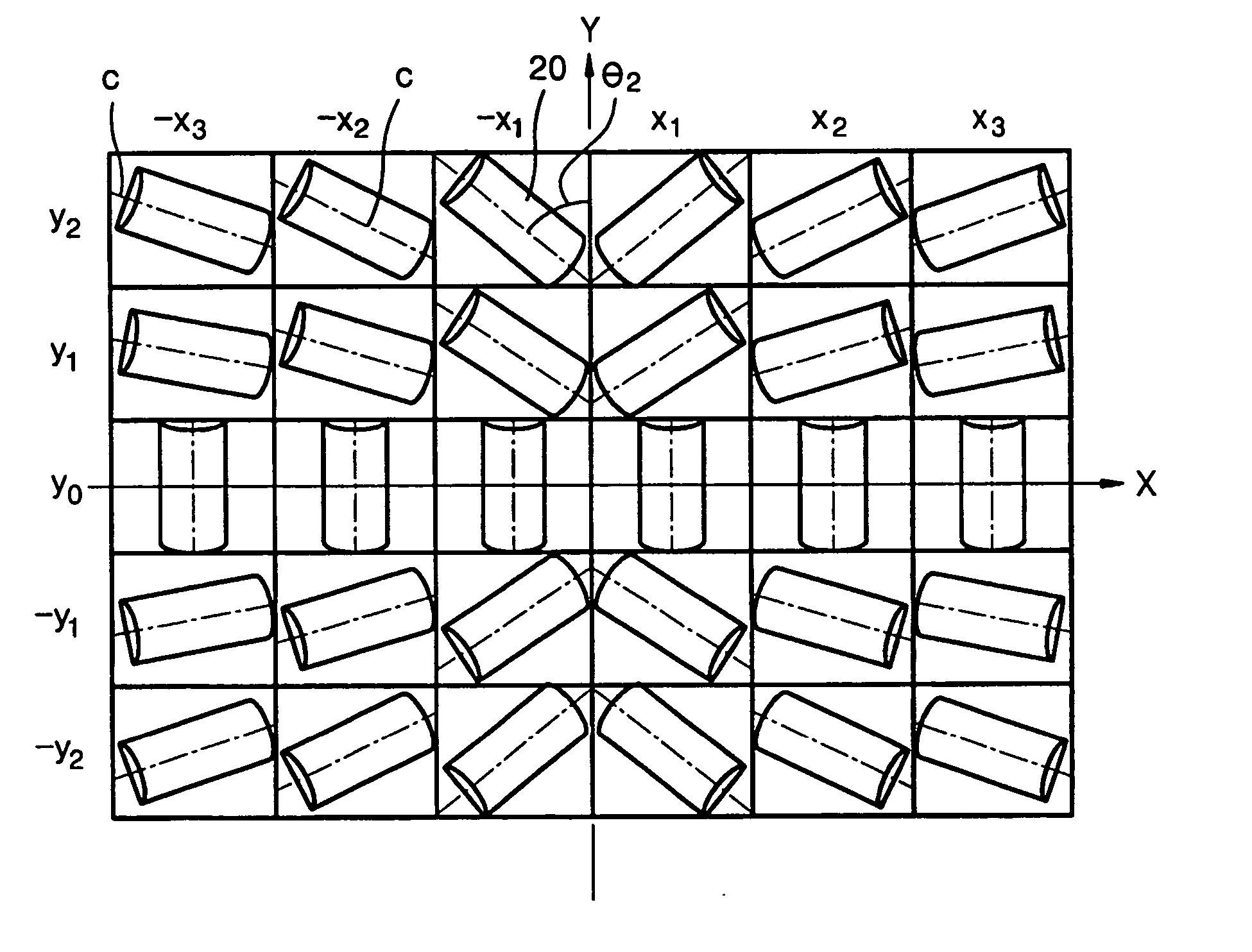
[0011] According to an aspect of the present invention, there is provided a cylinder lens array which is installed on a path of a light beam emitted from a light source and comprised of lens cells arrayed in such a way that their central axes are inclined at different angles, so that the light beam which diverges symmetrically with respect to its optical axis is aligned so as to reduce the angle of the divergence in a certain direction.
[0017] According to another aspect of the present invention, there is provided a projection system which forms an image by processing light emitted from a light source using a light valve in response to an input image signal and magnifies and projects the image onto a screen through a projection lens unit. The projection system includes a pair of cylinder lens arrays which are installed on a path of a light beam emitted from the light source and each are comprised of lens cells arrayed with central axes inclined at different angles, so that the light beam which diverges symmetrically with respect to its optical axis is aligned so as to reduce the angle of the divergence in a certain direction.

Problems solved by technology

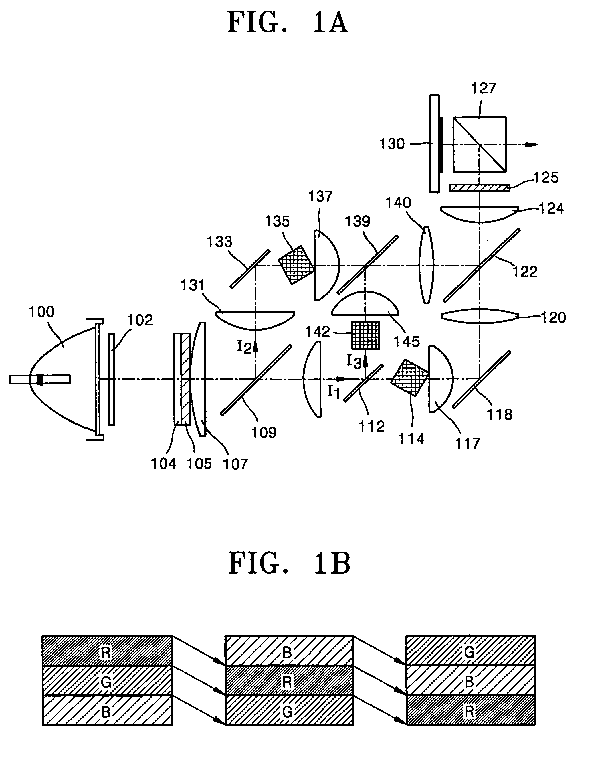
However, since single-panel projection systems use R, G, and B colors into which white light is sequentially divided, the light efficiency of each of the R, G, and B colors is only ⅓ of that of three-panel type projection systems.
Thus, the size of the conventional projection system increases, and its assembly is difficult.
Also, complicated light paths make alignment of optical axes difficult.
If the etendue at the starting point is greater than that at the ending point, the optical system becomes bulky.
If the etendue at the starting point is smaller than that at the ending point, light loss may be generated.
If the etendue of a light source is high, the range of angles at which light beams are incident upon a subsequent lens increases, making it difficult to properly configure the optical system.
However, changing the structure of a light source in order to reduce etendue requires a development of a new optimal light source and substitution of an existing light source, which cost money.
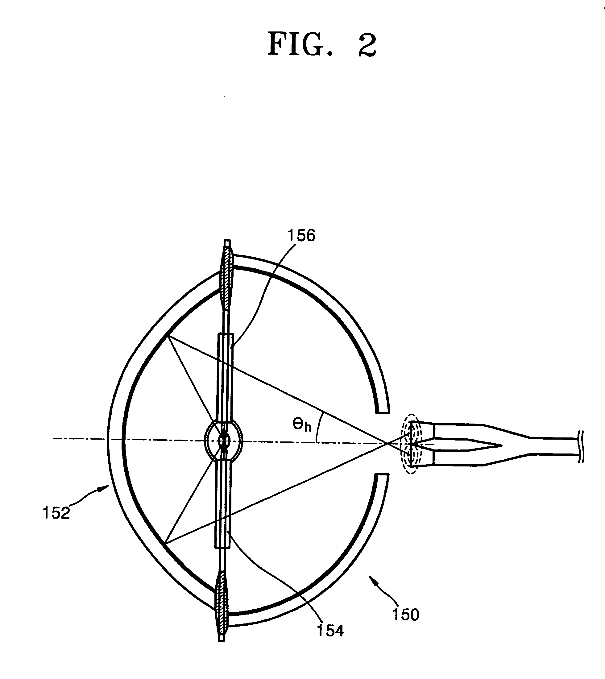
Also, light reflected by the retro reflector system 150 may return to the electrodes 154 and 156 and adversely affect the efficiency and durability of the light source.

Method used


Image

  • Cylinder lens array and projection system employing the same
  • Cylinder lens array and projection system employing the same
  • Cylinder lens array and projection system employing the same

Examples


first embodiment

[0033] Referring to FIG. 4, a cylinder lens array according to the present invention is comprised of lens cells 20 having different central axes so as to reduce etendue by aligning light distributed radially from a light source in one direction.

[0034] A process of changing a radial light distribution into an asymmetrical light distribution using a cylinder lens array according to the present invention will now be described. As shown in FIG. 3A, light emitted from a lamp light source has a radial distribution. Since an aspect ratio of a screen is 4:3 or 16:9, a light valve 10 included in a projection system generally has a rectangular shape and an aspect ratio of 4:3 or 16:9. In FIG. 3B, the radial distribution (d) of light emitted from a light source is compared with the rectangular shape of the light valve 10. As shown in FIG. 3B, because the light valve 10 is rectangular whereas light emitted from the light source has a radial distribution, some light is not incident on the light ...

second embodiment

[0043] As shown in FIG. 8, a cylinder lens array according to the present invention is comprised of lens cells 25. The lens cells 25 are arrayed in curved rows. In other words, the inclination of their central axes continuously increases from the middle to the left and right edges of the cylinder lens array. As the number of lens cells 25 increases, a light loss area between lens cells is minimized, thereby maximizing light efficiency.

[0044] If the central axes of adjacent lens cells aligned in one direction are inclined consecutively, the lens cells may be connected to one another along their central axes and incorporated into a single lens cell. FIG. 9 shows a cylinder lens array comprised of cylinder lenses 27 made up of lens cells connected to one another along their central axes. The formation of a cylinder cell 27 by lens cells contributes to simplify a process for manufacturing cylinder lens arrays.

[0045] The cylinder lens arrays according to the first and second embodiments...


PUM


Abstract

A cylinder lens array and a projection system adopting the same are provided. The cylinder lens array is installed on a path of a light beam emitted from a light source and is comprised of lens cells. The lens cells are arrayed with their central axes inclined at different angles, so that the light beam which diverges symmetrically with respect to its optical axis is aligned so as to reduce the angle of the divergence in a certain direction. The cylinder lens array is applicable to both single-panel projection systems and three-panel projection systems. In particular, when the cylinder lens array is applied to projection systems adopting a scrolling method, the effects of light alignment are maximized. Thus, etendue decreases, and light efficiency increases.

Description

BACKGROUND OF THE INVENTION [0001] The present invention relates to a cylinder lens array and a projection system employing the same, and more particularly, to a cylinder lens array providing increased light efficiency by reducing the etendue of an optical system by aligning light beams emitted from a light source, and a projection system adopting the cylinder lens array. [0002] Projection systems are classified into three-panel projection systems and single-panel projection systems according to the number of light valves that form an image by controlling the on-off operation of a high-output lamp used as a light source. Single-panel projection systems have a smaller optical system than the optical system of three-panel projection systems. However, since single-panel projection systems use R, G, and B colors into which white light is sequentially divided, the light efficiency of each of the R, G, and B colors is only ⅓ of that of three-panel type projection systems. Hence, attempts ...

Claims


Application Information

Patent Timeline
IPC IPC(8): F21V5/00G02B27/18G02B3/00G02B3/06G02B17/06G02B27/10G03B21/00
CPCG02B3/0037G02B3/0043G02B3/0062G02B27/145G02B17/061G02B27/102G02B27/1033G02B3/06G02B27/18
Inventor KIM, DAE-SIK
Owner SAMSUNG ELECTRONICS CO LTD
Learn More