Analog front end circuit with automatic sampling time generation system and method

a technology of automatic sampling and analog front end circuit, which is applied in the direction of code conversion, instruments, digital transmission, etc., can solve the problems of sampling errors, and affecting the quality of images

Inactive Publication Date: 2006-03-02
NOVATEK MICROELECTRONICS CORP
View PDF3 Cites 5 Cited by
  • Summary
  • Abstract
  • Description
  • Claims
  • Application Information

AI Technical Summary

Benefits of technology

[0010] One of the objectives of this invention is to provide an automatic clock generation system and method for automatically outputting a sampling signal and a holding signal to an analog front end circuit; it can quickly fi

Problems solved by technology

In addition, the synchronization state of the sampling clock signal 11 or the holding clock signal 13 and the sensor outputting signal10 also affects the quality of the sampling work; if the steady states Sa of the sampling clock signal 11 and the reference signal 12 are not synchronized, or if the holding clock signal and the level signal 14 are not synchronized, it will result in sampling errors and will affect the quality of the image.
However, the register can only store the invariable parameter; when there are chang

Method used


Image

  • Analog front end circuit with automatic sampling time generation system and method
  • Analog front end circuit with automatic sampling time generation system and method
  • Analog front end circuit with automatic sampling time generation system and method

Examples


Embodiment Construction

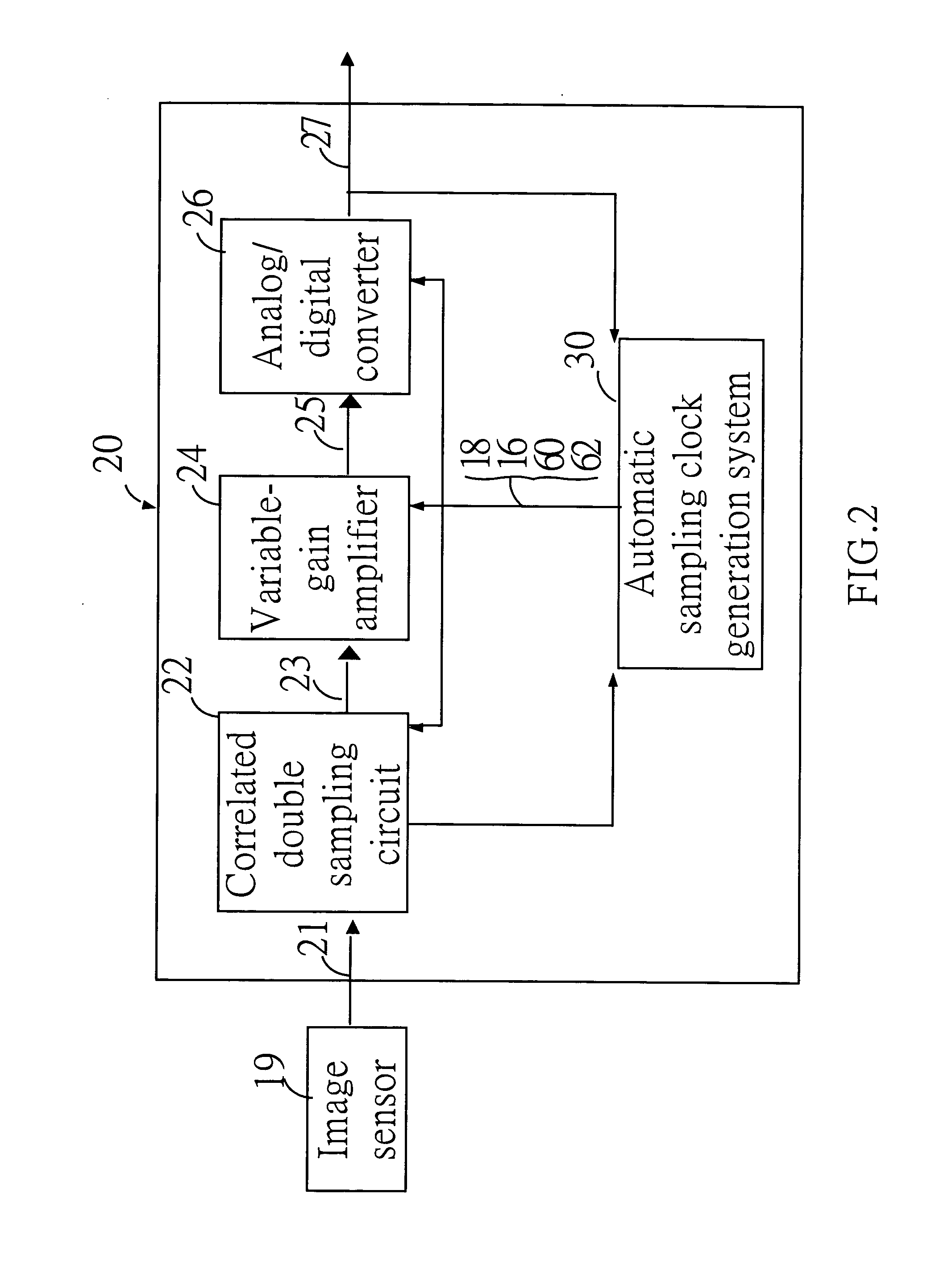
[0024] Referring to FIG. 2, FIG. 2 is a system block diagram of the automatic sampling clock generation system 30 used in an analog front end circuit 20. The automatic sampling clock generation system 30 is used for automatically generating a sampling signal 16 and a holding signal 18 to an analog front end circuit 20. The analog front-end circuit 20 transforms an analog signal 21 outputted from an image sensor 19 into a digital signal 27 according to the sampling signal 16 and the holding signal 18 of the automatic sampling clock generation system 30. The analog front end circuit 20 comprises a correlated double sampling circuit 22, a variable-gain amplifier 24, and an analog / digital converter 26.

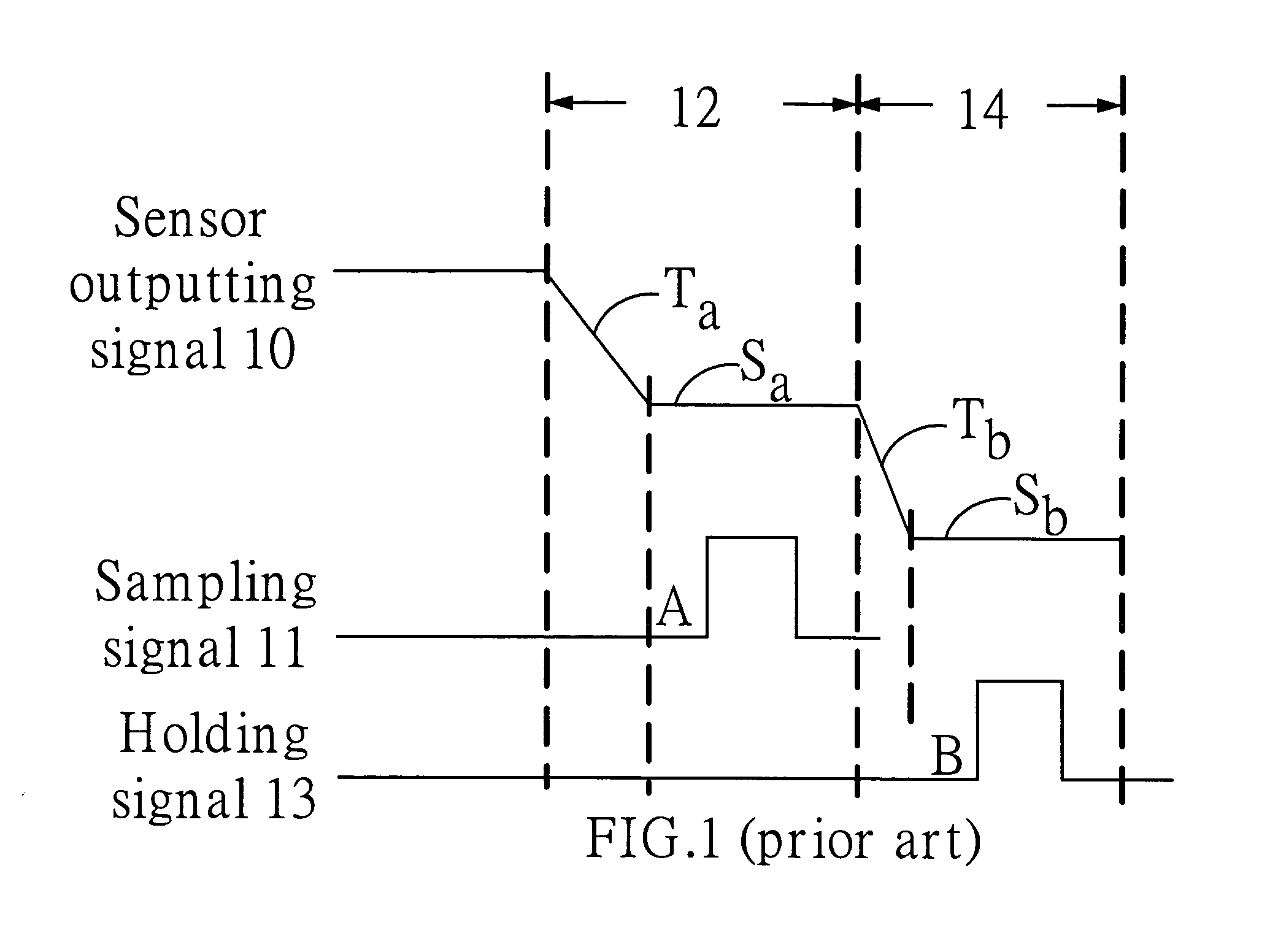
[0025] Referring to FIG. 1 and FIG. 2, the outputted analog signal 21 of the image sensor 19 periodically contains an level signal 14 and a reference signal 12. A correlated double sampling circuit 22 generates a processing signal 23 by utilizing the sampling signal 16 and the holding sig...


PUM


Abstract

An automatic clock generation system is used for automatically outputting a sampling signal and a holding signal to an analog front end circuit and for sampling the analog signal. The clock generation system comprises a clock generator generating a plurality of clock signals and a comparing module. According to the plurality of clock signals, the comparing module compares the analog signal with a first reference signal and outputs a first comparison signal. The comparing module further compares the digital signal outputted by the analog front end circuit with a second reference signal and outputs a second comparison signal. The clock generator selectively outputs a first clock signal, corresponding to the first comparison signal, of the plurality of clock signals as the sampling signal when the first comparison signal received by the clock generator is at a high state. The clock generator further selectively outputs a second clock signal, corresponding to the second comparison signal, of the plurality of clock signals as the holding signal when the second comparison signal received by the clock generator is at the high state.

Description

BACKGROUND OF THE INVENTION [0001] 1. Field of the Invention [0002] This present invention relates to an automatic sampling clock generation system; it is especially about a clock generation system for automatically generating a sampling signal and a holding signal to an analog front end circuit. [0003] 2. Description of the Prior Art [0004] Because the outputting signal of general image sensors periodically contains a level signal and a reference signal, an analog front end circuit usually utilizes the format of the correlated double sampling to sample the outputting signal of the image sensor; it also amplifies and transforms the result into a digital signal for the follow-up element processing. [0005] Referring to the system shown in FIG. 1, FIG. 1 is a working diagram of a sensor outputting signal 10, a sampling clock signal 11, and a holding clock signal 13 of the prior art. Sensor outputting signal 10 of the sensor periodically includes a reference signal 12 and an level signa...

Claims


Application Information

Patent Timeline
IPC IPC(8): H04L7/00H03L7/06H04N1/028
CPCH03M1/1255
Inventor CHOU, KUO-YU
Owner NOVATEK MICROELECTRONICS CORP
Why Eureka
Try Eureka