Helical flute end mill with multi-section cutting edge

a technology of end mills and helical flutes, which is applied in the direction of metal working equipment, metal-working apparatus, milling equipment, etc., can solve the problems that the combination may not provide a desirable milling feed rate for a different type of material, and achieve the effect of facilitating chip ejection and enhancing chip removal

Active Publication Date: 2006-03-02
BERKSHIRE PRECISION TOOL
View PDF15 Cites 40 Cited by
  • Summary
  • Abstract
  • Description
  • Claims
  • Application Information

AI Technical Summary

Benefits of technology

[0010] An advantage of the present invention end mill is that the end mill can be specifically configured to a particular application. The present invention uses constant angle helix portions, arcuate transition sections, and helix indexing to create the desired chip size for a particularly milling application. For example, a desirable milling feed rate can be accomplished with a first material given an end mill with a particular combination of constant angle helix portions, arcuate transition sections, and helix indexing. That same combination may not, however, provide a desirable milling feed rate for a different type of material. The present invention enables the selection of a combination of flute features that will provide desirable end mill performance.
[0011] Another advantage provided by the present invention end mill is that it enhances chip removal. The present invention enables an optimum size chip to be produced, which size facilitates chip ejection.
[0012] These and other objects, features and advantages of the present invention will become apparent in light of the detailed description of the best mode embodiment thereof, as illustrated in the accompanying drawings.

Problems solved by technology

That same combination may not, however, provide a desirable milling feed rate for a different type of material.

Method used


Image

  • Helical flute end mill with multi-section cutting edge
  • Helical flute end mill with multi-section cutting edge
  • Helical flute end mill with multi-section cutting edge

Examples


Embodiment Construction

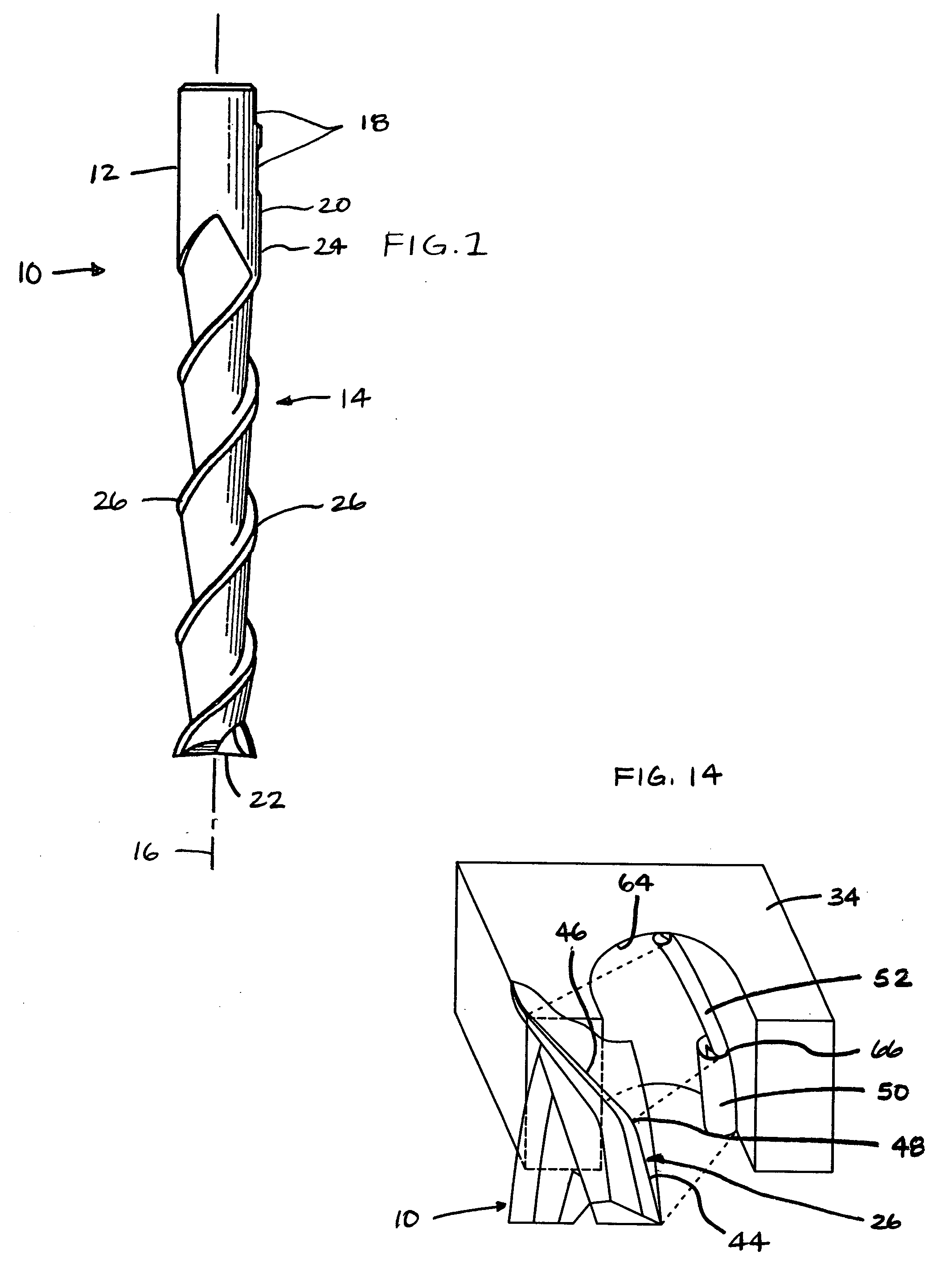
[0023] Now referring to FIG. 1, an end mill 10 is shown that includes a shank section 12 and a fluted section 14, both of which extend along an axis of rotation 16 of the end mill 10. The shank section 12 is essentially cylindrical in shape and possesses two rectangular grooves 18 cut into its outer surface. The grooves 18, although not required, facilitate retention of the end mill 10 within certain types of rotary driven apparatus (e.g., a milling machine). Acceptable end mill 10 materials include, but are not limited to, high strength steel / cobalt, ceramics, carbides, etc.

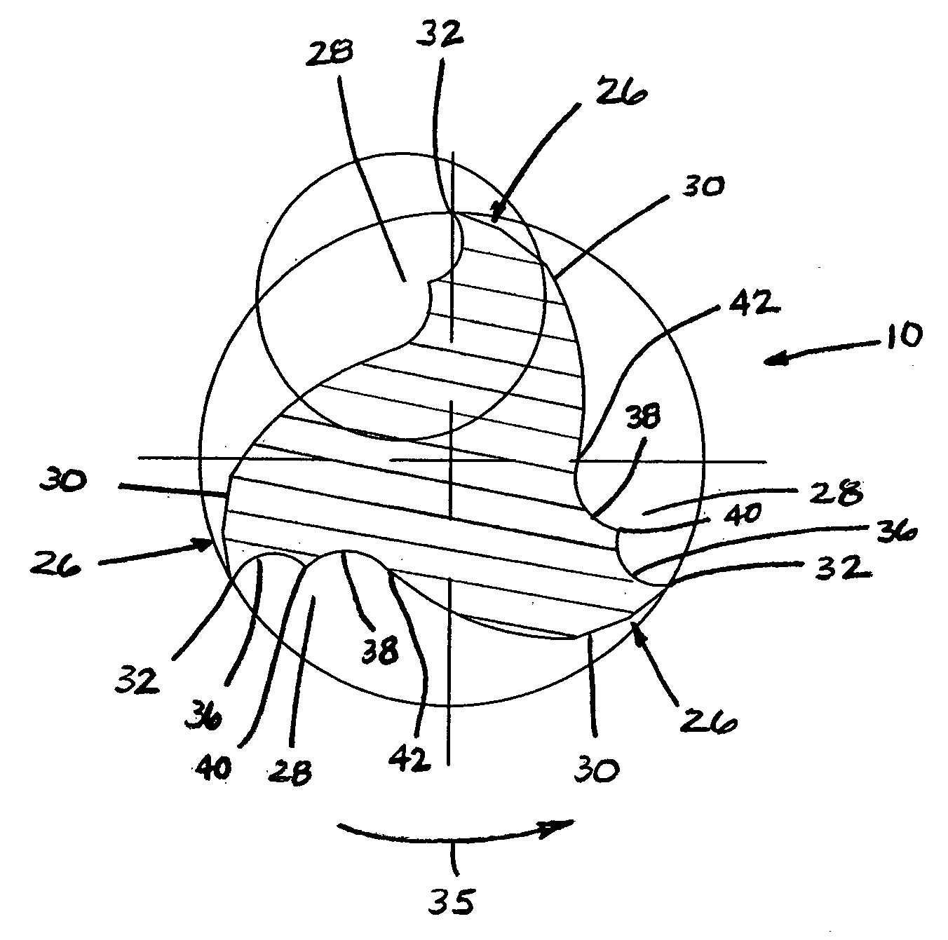
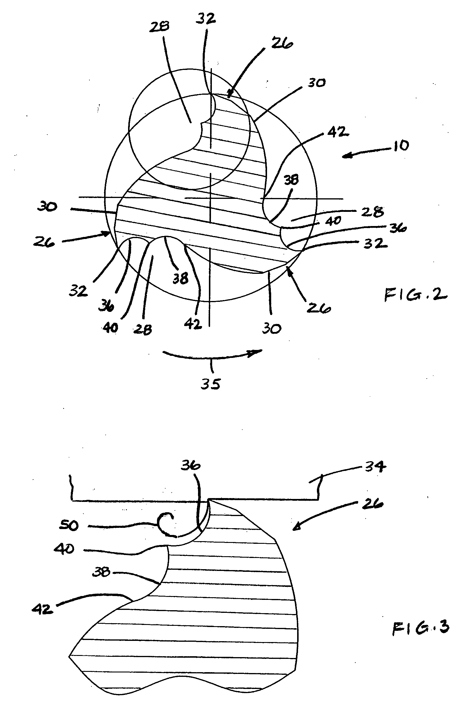
[0024] The fluted section 14 of end mill 10 has a first end 20 integrally attached to the shank section 12, a second end 22, and an outer surface 24. A plurality of helical teeth 26 are disposed along the outer surface 24 of the fluted section 14. FIG. 1 illustrates an embodiment having two helical teeth 26. FIG. 2 illustrates an embodiment having three helical teeth 26. Other embodiments may have more than thr...


PUM


Abstract

An end mill is provided that includes a shank section and a fluted section. One or more helical teeth are disposed along an outer surface of the fluted section. Each helical tooth has a cutting surface and a relief wall that intersect to form an angle defining a helical cutting edge. The cutting surface of each helical tooth includes a first section, a second section, and a take-off peak disposed between the first section and second section. The cutting edge of each helical tooth includes a first portion having a first constant angle, and a second portion having a second constant angle unequal to the first constant angle, and an arcuate transition section connecting the first portion and second portion. Some embodiments of the present invention include more portions than the aforesaid first and second portions.

Description

BACKGROUND OF THE INVENTION [0001] 1. Technical Field [0002] The present invention relates machine tool rotary cutting tools in general, and to end mills in particular. [0003] 2. Background Information [0004] A variety of end mills for use with rotating milling cutters are available and well known. Depending on design, such end mills are generally used in right hand cutting, right hand spiral and center cutting. [0005] Some prior art end-mills have helical flutes that follow a single continuous cutting edge angle. For example, it is known in the art to form flutes at a low helix angle or a high helix angle. A “low helix” (or low helical flute) is a flute that helically “winds” around a cylinder at an angle of no more than 45 degrees. A “super” low helical flute would be a flute that winds around a cylinder at an angle of at no more than 15 degrees. A “high helix” (or high helical flute) is a flute that helically winds around a cylinder at an angle of greater than 45 degrees, while a...

Claims


Application Information

Patent Timeline
Patent Type & Authority Applications(United States)
IPC IPC(8): B23C5/10
CPCB23C5/10B23C2210/0485Y10T407/1966Y10T407/196Y10T407/1946B23C2210/0492
Inventor FLYNN, CLIFFORD M.
Owner BERKSHIRE PRECISION TOOL
Why Eureka
Try Eureka