
Tire building method and stitcher device

a building method and a technology applied in the field of a stitching device and a building method, can solve the problems of obstructing the enhancement of productivity, prolonging the building cycle time, shrinking of the members, etc., and achieves a well-balanced manner

Inactive Publication Date: 2006-03-09
TOYO TIRE & RUBBER CO LTD
View PDF7 Cites 34 Cited by
  • Summary
  • Abstract
  • Description
  • Claims
  • Application Information

AI Technical Summary

Benefits of technology

[0016] In the above method, the pressing part or member of the stitcher device for pressing and bonding the tire members is formd of pneumatic-tire roller and hence, the pressing is made at an approximately uniform pressing force over the whole pressing surface by way of inner pressure of the pneumatic-tire roller. Thus, even when a width of the roller is increased, there arises no difference in the pressing force within the pressing surface and the pressing area may be increased without any problem. Accordingly, a moving speed of the roller when the roller is to be moved in the widthwise direction may be increased and hence, even when the pressing for the bonding are to be applied on whole of tire members in a large area. Such pressing for the bonding may be preformed in a short time, whereby a building cycle time is shortened thus contributing to the enhancement of the productivity.
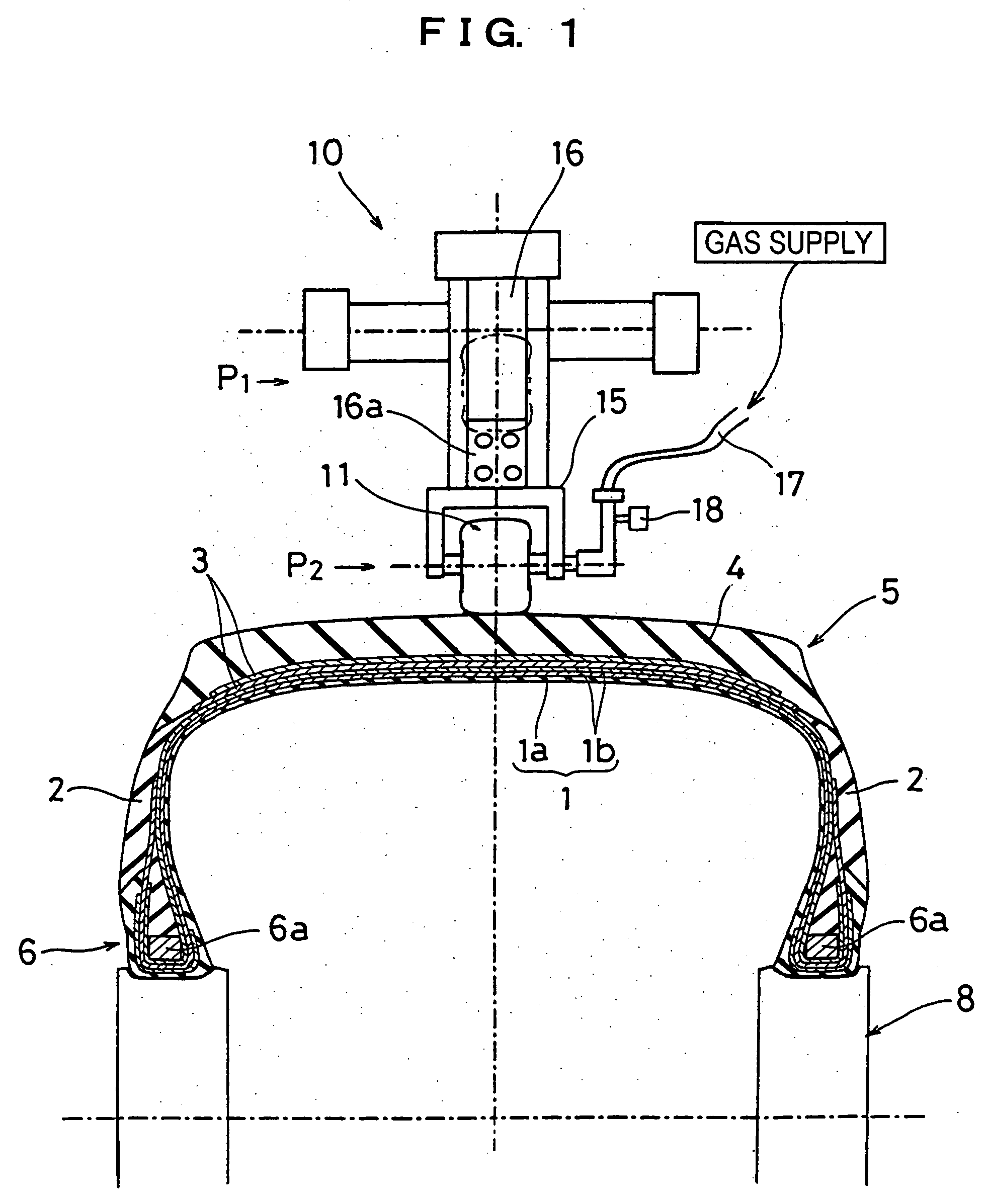
[0026] In another preferred embodiment, the stitchre device further comrises: a gas supply system connected to a hollow inside of the pneumatic-tire roller; and a pressure switch provided at a portion of a gas supply line from the gas supply system and capable of detecting the inner pressure; gas supply through the pressure switch being controlled based on said detecting as to keep the inner pressure as constant. In this way, the press-contacting is made with a constant pressure and in a well-balanced manner all over the outer face of the tire.

Problems solved by technology

Meanwhile, when the inner-member laminate is built by stacking a plurality of tire inner members at the same building position, a building cycle time is prolonged and this obstructs the enhancement of the productivity.
By such extrusion, there arise drawbacks such as the distortion and the shrinkage of the members.
Consequently, tire building cycle time is prolonged thus obstructing the enhancement of the productivity.
As a result, the uniformity of tire product is adversely affected.
Thus, the ribbons are susceptible to deformation as to undermine stability in layout of the tire members in tire building; and improvement in the tire building method is required.

Method used


Image

  • Tire building method and stitcher device
  • Tire building method and stitcher device
  • Tire building method and stitcher device

Examples


Embodiment Construction

[0033] An embodiment of the present invention explained hereinafter, in conjunction with the drawings.

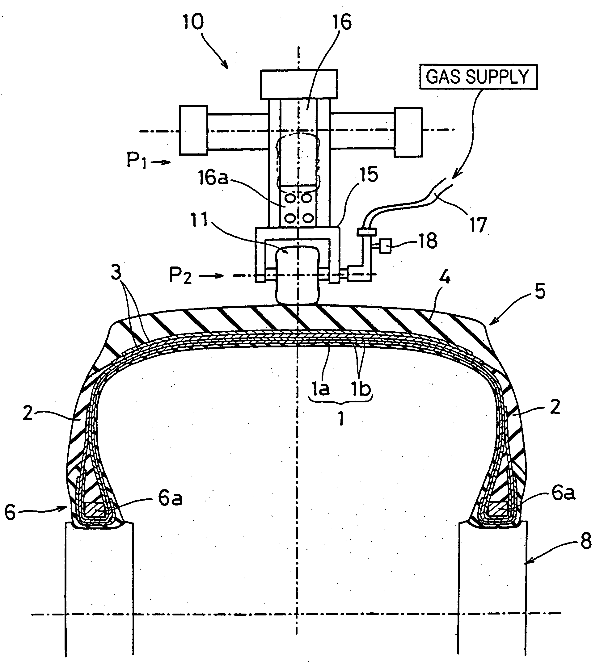
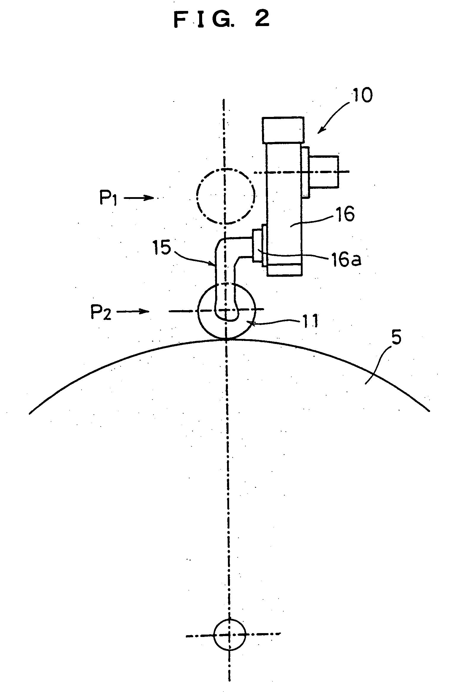
[0034] In FIG. 1 and FIG. 2, numeral 1 indicates a cylindrical inner-member laminate which is formed by stacking inner tire members including an inner liner 1a, carcass plies 1b, a chafer and the like; numeral 2 indicates side wall rubbers which are stacked on the inner-member laminate 1; numeral 3 indicates a belt which is one of the outer tire members stacked on the inner-member laminate 1 in a state that inner-member laminate 1 is deformed as bulged; numeral 4 indicates a tread rubber; and numeral 5 indicates a green tire as a stacked body of these tire members. Numeral 6 indicates bead portions and numeral 6a indicates bead cores. Numeral 8 indicates a rotary support body such as a building drum or the like which supports the inner-member laminate 1 as to be deformed as bulged, at its bead portions 6. The green tire 5 is built by stacking the outer tire members such as the belt...


PUM

PropertyMeasurementUnit
Pressureaaaaaaaaaa
Distanceaaaaaaaaaa

Abstract

A tire building method and a stitcher device therefore, which are aiming for achieving reliable pressing for bonding between a plurality of tire members all over outer face of the tire members, without forming a void between them, even though the outer face of the tire members have ups and downs, so as to curb strain in a carcass cord and to improve process efficiency. The method comprising: laying one or more of the tire members on a rotary support body such as a building drum; and press-contacting a press-contact part of a stitcher device on said one or more of the tire members on the rotary support while the rotary support being rotated, so as to bond together said one or more of the tire members; said press-contact part being a pneumatic-tire roller maintained with a certain level of inner pressure.

Description

TECHNICAL FIELD [0001] The present invention relates to a tire building method and a stitcher device which is used in the tire building method. BACKGROUND ART [0002] Conventionally, as a building method of tires, there has been known a two-stage building method for building a tire. Plase see, for example, JP-A-1995-60868 and JP-A-2003-231187. The two-stage building method is as follows: Inner tire members such as an inner liner, a chafer, carcass plies and the like are laid to be stacked on a building drum capable of expanding and shrinking a diameter thereof, as to form a cylindrical laminate of the inner tire members. Onto this inner-member cylindrical laminate, made are a setting of beads, turn-up folding of the carcass plies, stacking of side wall rubbers and the like as to build an inner-member laminate which is referred to as a “green casing” and also as a “carcass green”. The inner-member laminate is transferred to a second building drum and is deformed into a toroidal shape ...

Claims


Application Information

Patent Timeline
IPC IPC(8): B29D30/14B29D30/28
CPCB29D30/28B29D30/14
Inventor KUDO, SHIGEOTATARA, TETSUOTANABE, MASAMI
Owner TOYO TIRE & RUBBER CO LTD
Learn More