Long travel, high force combination spring

Inactive Publication Date: 2006-03-09
ANCHOR LAMINAAMERICA INC
View PDF13 Cites 19 Cited by
  • Summary
  • Abstract
  • Description
  • Claims
  • Application Information

AI Technical Summary

Benefits of technology

[0014] It is the object of the present invention to provide a mechanical spring combination having a large travel, with an initial low spring rat

Problems solved by technology

Very stiff coil springs have limited available travel for a given space due to the thick cross section required to develop a high spring rate.
However, nitrogen springs have several disadvantages, including their initial high cost and their need to be serviced regularly, and the fact that high cycle rates are not possible due to excessive heat build up.
The inclusion of machined ca

Method used


Image

  • Long travel, high force combination spring
  • Long travel, high force combination spring
  • Long travel, high force combination spring

Examples


Example

[0030] In the following detailed description, certain specific terminology will be employed for the sake of clarity and a particular embodiment described in accordance with the requirements of 35 USC 112, but it is to be understood that the same is not intended to be limiting and should not be so construed inasmuch as the invention is capable of taking many forms and variations within the scope of the appended claims.

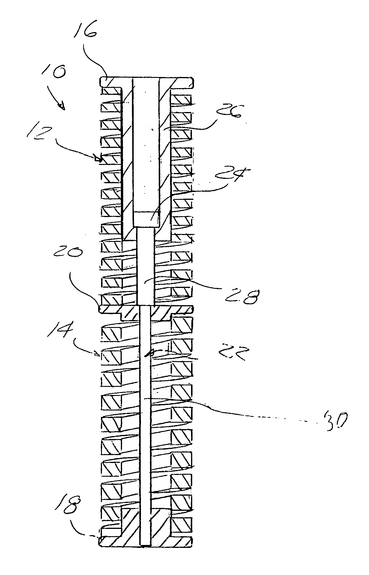
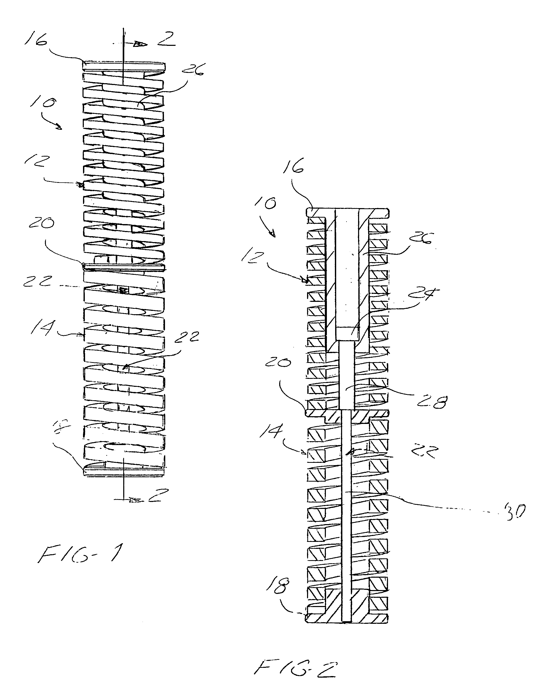
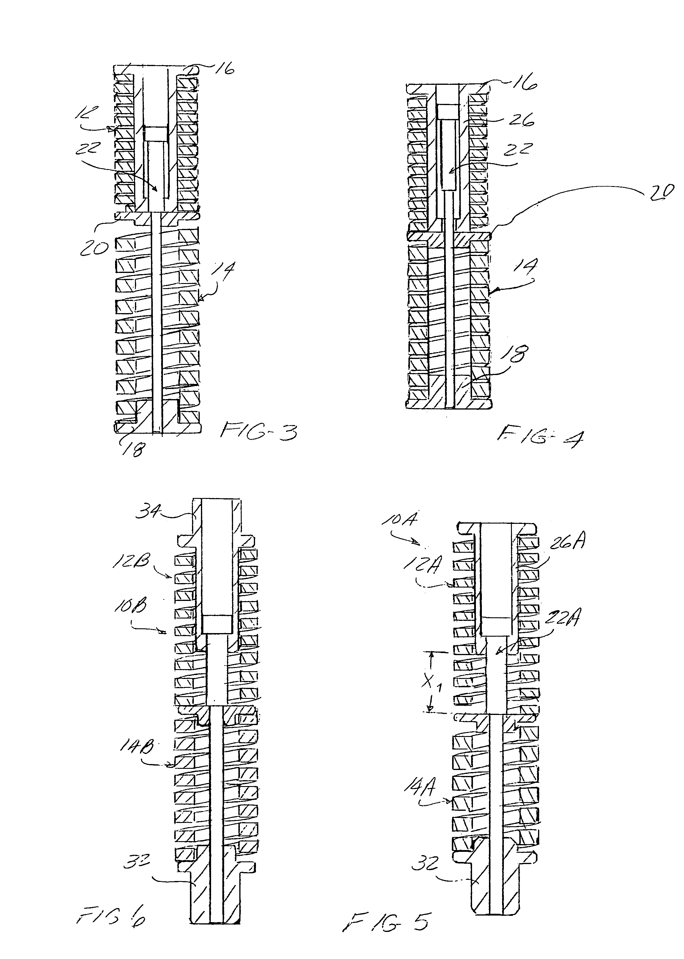
[0031] Referring to the drawings, and particularly FIGS. 1-4, a combination spring 10 according to the present invention is shown, including two elongated, differing rate helically wound coil compression springs 12 and 14 connected together end-to-end.

[0032] Each spring 12, 14 is held compressed between respective end flanges 16, 18 and a common intermediate flange 20.

[0033] End flange 16 is held to the common intermediate flange 20 by a stepped diameter pin 22 having a head 24 slidable within a plunger 26 connected to the associated end flange 16.

[0034] The plunger...


PUM


Abstract

A long travel, varying spring rate combination spring includes two differing rate springs connected end-to-end in such a way that the lower rate spring is compressed until positive engagement of a plunger with an intermediate flange member occurs with the higher rate spring thereafter compressed. Each spring may be assembled separately and connected together with a coupling to create a combination spring, allowing various springs to be combined to meet the requirements of a particular application.

Description

BACKGROUND OF THE INVENTION [0001] This invention concerns springs and more particularly mechanical compression springs as are used to provide a return force such as in cam operated dies. [0002] In cam operated tooling installed on dies in forming presses, a slide is operated by the press motion to drive a tool used to form a feature on a part. [0003] One or more return springs are compressed as the tool is advanced by a camming action produced by the slide. When the press platens are moved apart, the compressed spring or springs act to retract the slide. [0004] In metal forming, it sometimes takes considerable force to withdraw a piercing tool from the part, such that a high return spring force is required at the start of the return motion. At the same time, a substantial slide travel is required. Very stiff coil springs have limited available travel for a given space due to the thick cross section required to develop a high spring rate. [0005] This required combination of long tra...

Claims


Application Information

Patent Timeline
IPC IPC(8): F16F1/06
CPCF16F1/041F16F3/04F16F1/125F16F1/042
Inventor CHUN, VICTOR L.TAYLOR, BRIAN LEELEIBMAN, ALEXANDER B.HAJJAR, MICHAEL
Owner ANCHOR LAMINAAMERICA INC
Why Eureka
Try Eureka