
Recording apparatus

Inactive Publication Date: 2006-03-09
SEIKO EPSON CORP
View PDF21 Cites 4 Cited by
  • Summary
  • Abstract
  • Description
  • Claims
  • Application Information

AI Technical Summary

Benefits of technology

[0009] It is therefore an object of the invention to provide a recording apparatus comprising an elongated member having a high flexural and torsional rigidity and a high straightness and a method of manufacturing such a elongated member.
[0014] Preferably, the synthetic resin is comprised of an additive enhancing stiffness of the shaft portion.
[0021] Forming the shaft portion of the feeding roller with the hollowed portion, it is possible to make an outer peripheral face thereof uniform without deficiency such as a recess. In addition, there can be obtained many advantages such as enhancement in a gripping force with respect to the sheet, prevention of damage on the sheet and improvement on an appearance quality of the roller.
[0023] Preferably, the synthetic resin is comprised of an additive enhancing stiffness of the hopper body.
[0027] With this configuration, it is not necessary to provide a reinforcement member (e.g., sheet metal) for enhancing the rigidity of the hopper body. Accordingly, it is possible to obtain many advantages such as reduction of manufacturing costs, reduction of a device weight, and elimination of sound generated from the sheet metal due to vibrations of the apparatus. Moreover, the hollowed space can be utilized as a wiring path of a wire harness, a passage for waste ink, or the like.

Problems solved by technology

This causes increase of the dimension and the weight of the discharging roller.
Therefore, there is anxiety that deformation such as a flexure is produced in the discharging roller 1.
Therefore, in case that the above flip phenomenon is produced, a bad influence is exerted on recording accuracy.
This causes deformation or the rigidity reduction of the discharging roller surface.
Moreover, if flashes are formed on an outer circumferential surface of the shaft portions 20 and the cylindrical body 30 at the plastic molding process performed by the gas injection method, for example, there is anxiety that the flashes cause sliding load increase of a bearing portion or deterioration of sheet feeding accuracy.

Method used


Image

  • Recording apparatus
  • Recording apparatus
  • Recording apparatus

Examples


first embodiment

[0069] As shown in FIG. 6, in a die 200 used in molding of the shaft portion 163a of the discharging roller 163, according to the invention, cavity portions 201 and 202 are formed in order to mold one shaft portion 163a of the discharging roller 163, and the die 200 comprises an upper die 210 and a lower die 220 that are divided in the radial direction of the discharging roller 163. Here, since the conventional shaft portion of the discharging roller, formed of metal is high in rigidity, distortion can be prevented by double point support structure in which both ends are supported. However, since the shaft portion 163a of the discharging roller 163 according to the invention is formed of plastics that is lower in rigidity than the metal, five point support structure in which not only the both ends but also intermediate portions are supported is adopted to prevent the distortion.

[0070] Since molding accuracy of each bore part in the shaft portion 163a of the discharging roller 163 af...

second embodiment

[0078] Further, as the injection method, a gas injection method can be adopted. FIG. 12 shows this configuration as the invention. To a die attaching portion of an injection molding machine of this embodiment, a die 400 and a die 450 are attached. The die 400 has the similar structure as the die 200, in which cavity portions 401, 402 for molding one shaft portion 163a of a discharging roller 163 are formed. An auxiliary cavity 451 is attached to an exhaust port 404.

[0079] Under a condition that the cavity portions 401, 402 of the die 400 are heat regulated at a predetermined temperature, the predetermined amount of the melted plastic is injected from an injection port 403 of the die 400. Subsequently, the predetermined amount of gas is injected from the injection port of the die 400. Hereby, a plastic outer surface coming into contact with the inner surfaces of the cavity portions 401, 402 is quickly cooled and pressed by gas pressure from the plastic inside. Therefore, the plastic ...


PUM


Abstract

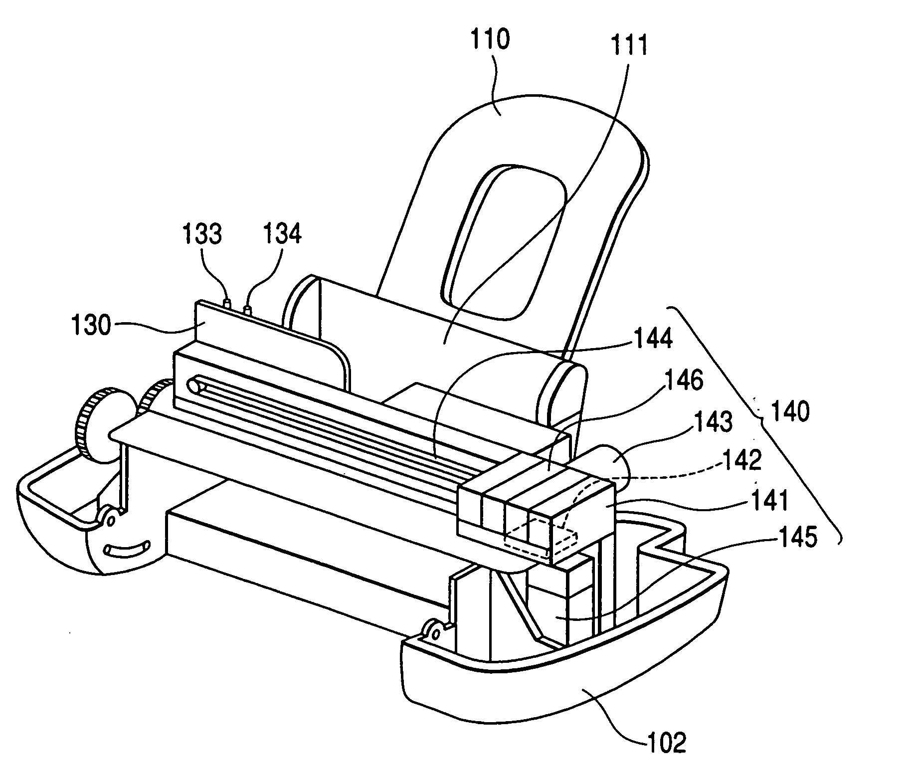
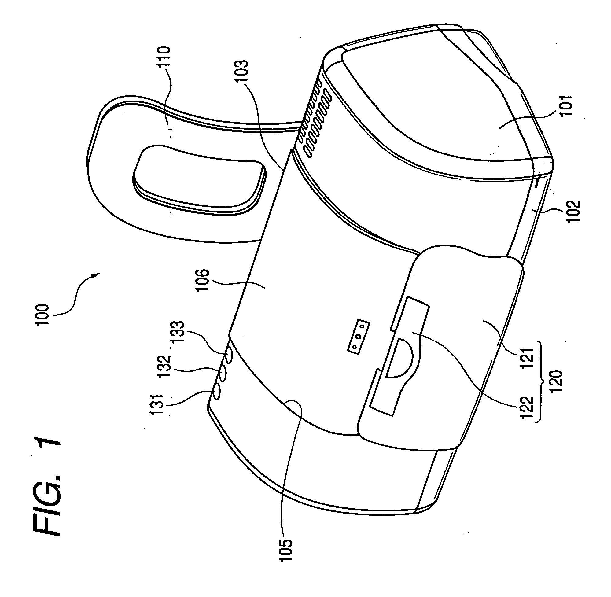
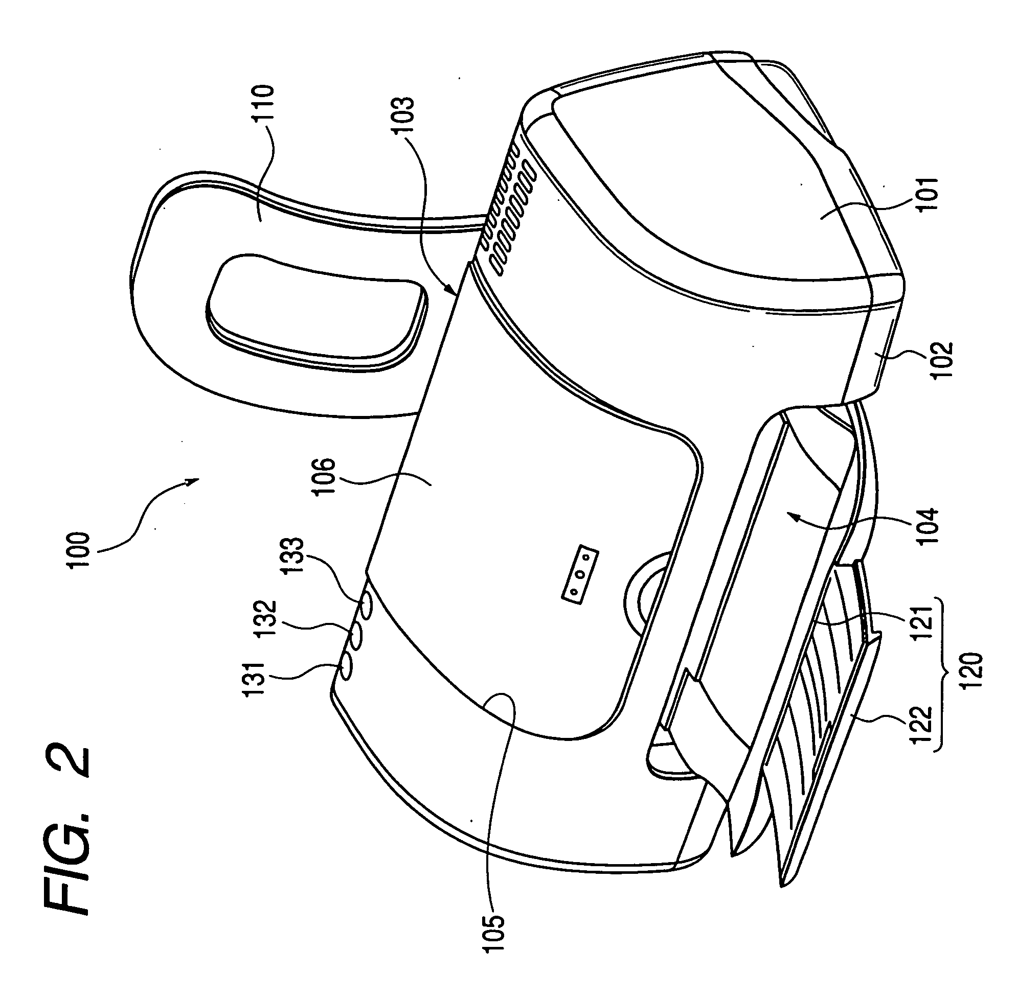
A feeding roller is adapted to feed a recording medium to a recording section provided in a recording apparatus. A shaft portion of the feeding roller is made of synthetic resin and formed with a hollowed portion. A roller portion is formed on an outer periphery of the shaft portion. A hopper is adapted to support the recording medium to be fed to the recording apparatus. The body of the hopper is made of synthetic resin and formed with a hollowed portion extending in a longitudinal direction of the recording apparatus.

Description

CROSS-REFERENCE OF THE APPLICATION [0001] This is a continued-in-part application of Ser. No. 11 / 144,823 filed on Jun. 6, 2005 which is a continuation application of Ser. No. 10 / 878,396 filed on Jun. 29, 2004 which is a divisional application of Ser. No. 10 / 388,177 filed on Feb. 24, 2003.BACKGROUND OF THE INVENTION [0002] The present invention relates to a recording apparatus comprising: a feeder including a hopper and a feeding roller to feed a recording medium to a recording section; and a discharging roller which discharges the recording medium. The present invention also relates to a method of manufacturing an elongated member such as the hopper, the feeding roller and the discharging roller which are to be incorporated in the recording apparatus. [0003] An ink jet printer that is one of recording apparatuses is generally constituted so as to supply a sheet (recording medium) stored in a sheet feeding tray to a sheet feeding roller, transport the supplied sheet to a recording se...

Claims


Application Information

Patent Timeline
IPC IPC(8): B41J2/01
CPCB65H3/0638B41J13/02
Inventor NODA, SATOSHIKANZAWA, TAKAOHAMAKAWA, HIROSHIOKUDA, YASUMICHIKOBAYASHI, YOSHIHIRO
Owner SEIKO EPSON CORP
Learn More