Heat detector for main board

Inactive Publication Date: 2006-03-09
ASMEDIA TECHNOLOGY INC
View PDF4 Cites 2 Cited by
  • Summary
  • Abstract
  • Description
  • Claims
  • Application Information

AI Technical Summary

Benefits of technology

[0012] As mentioned above, the heat detector for a main board of the invention employs the current generation unit to substitute the conventional referenc

Problems solved by technology

However, a problem induced by the powerful functions and fast processing speed is the complicated layout of a circuit board and the increasing temperature on the CPU.
The complicated layout results in insufficient circuit space on the circuit board.
The increasing temperature may result in burning of the CPU or peripheral elements.
However, i

Method used


Image

  • Heat detector for main board
  • Heat detector for main board
  • Heat detector for main board

Examples


Embodiment Construction

[0017] The present invention will be apparent from the following detailed description, which proceeds with reference to the accompanying drawings, wherein the same references relate to the same elements.

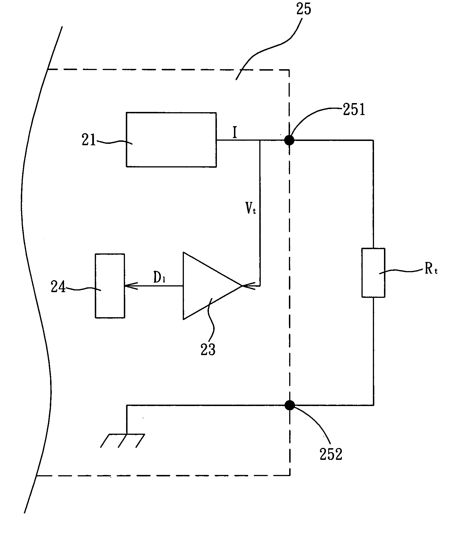
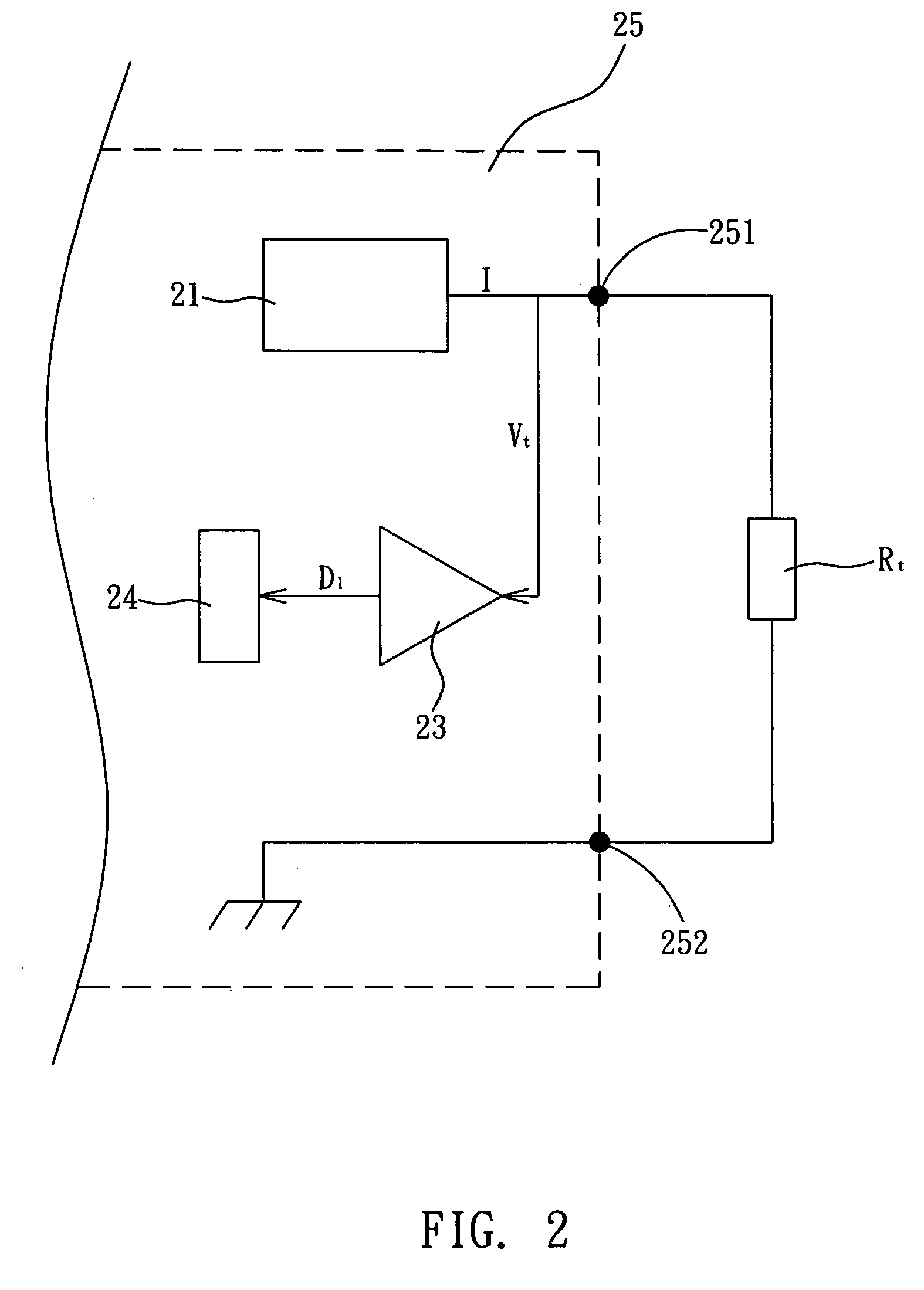
[0018] With reference to FIG. 2, a heat detector for a main board according to a preferred embodiment of the invention at least includes a current generation unit 21, a heat perception element Rt, an analog to digital converter (ADC) 23, and a control unit 24. In this embodiment, the current generation unit 21, the ADC 23, and the control unit 24 are integrated in a chip 25.

[0019] The current generation unit 21 is used to generate a current signal I. The heat perception element Rt electrically connects to the current generation unit 21 and generates an analog signal Vt according to the current signal I. Herein, the analog signal Vt is a voltage value. In this embodiment, the heat perception element Rt is a thermal resistor, which varies its resistance value with temperature.

[0020]...


PUM


Abstract

A heat detector for a main board at least comprises a current generation unit, a heat perception element, and an analog to digital converter (ADC). The current generation unit generates at least one current signal. The heat perception element electrically connects to the current generation unit and generates an analog signal according to the current signal. The ADC electrically connects to the current generation unit and the heat perception element. The ADC is for converting the analog signal into a digital signal.

Description

BACKGROUND OF THE INVENTION [0001] 1. Field of Invention [0002] The invention relates to a heat detector for a main board and, in particular, to a current heat detector for a main board. [0003] 2. Related Art [0004] With the advance in the electronic technology, the central processing unit (CPU) become more powerful in its functions and faster in its processing speed. However, a problem induced by the powerful functions and fast processing speed is the complicated layout of a circuit board and the increasing temperature on the CPU. The complicated layout results in insufficient circuit space on the circuit board. The increasing temperature may result in burning of the CPU or peripheral elements. [0005] Regarding to the temperature control, one method is to add a fan for the CPU. However, if the rotational speed of the fan is not properly controlled, the fan may always rotate at full speed and waste the power even when the temperature of the CPU is lower. Therefore, it is necessary t...

Claims


Application Information

Patent Timeline
IPC IPC(8): H02H7/00
CPCG06F1/206G01K7/20
Inventor HUNG, CHIH-JENCHENG, HSU-HUANGMEI, TSORNG-YANG
Owner ASMEDIA TECHNOLOGY INC
Why Eureka
Try Eureka