
Flexible connection substrate and folding electronic apparatus

a technology of flexible connection substrate and electronic equipment, which is applied in the direction of printed circuit grounding, electrical apparatus casing/cabinet/drawer, cross-talk/noise/interference reduction, etc., can solve the problems of unfavorable manufacture of connection by jumper wires, the routing of jumper wires inside the hinge is extremely problematic, and the reliability of the secure connection of the circuit substra

Inactive Publication Date: 2006-03-09
NEC CORP
View PDF15 Cites 29 Cited by
  • Summary
  • Abstract
  • Description
  • Claims
  • Application Information

AI Technical Summary

Benefits of technology

[0009] The present invention has as an object a flexible connection substrate that is used for connecting each of the circuit substrates inside two cases in a folding electronic apparatus that allows routing through the hinge regardless of the construction of the hinge, and moreover, that eliminates the need for soldering such as for jumper lines.
[0010] It is another object of the present invention to provide a flexible connection substrate and folding electronic apparatus that enable a reduction of the difference in ground voltage between two circuit substrates.
[0011] It yet another object of the present invention to provide a flexible connection substrate having a construction that has the effect of shielding noise that is generated by the first flexible substrate.

Problems solved by technology

However, considerations relating to the folding construction and to more compact construction have limited the width and length of the ground pattern in a folding portable telephone, raising problems of reliability regarding the secure connection of the circuit substrates.
There are now folding portable telephones having a variety of hinge constructions, including folding portable telephones in which the routing of jumper wires inside the hinge is extremely problematic.
In addition, connection by jumper wires is not preferable from the standpoint of manufacture due to limitations in connection methods, such as soldering.
However, the first and second flexible connection substrates are constructions that are completely independent of each other, and this publication discloses nothing more than the independent connection of signal lines and ground lines.
Further, the radio device gives no consideration to shielding the noise that is generated from the first flexible connection substrate for connecting signal lines.

Method used


Image

  • Flexible connection substrate and folding electronic apparatus
  • Flexible connection substrate and folding electronic apparatus
  • Flexible connection substrate and folding electronic apparatus

Examples


first embodiment

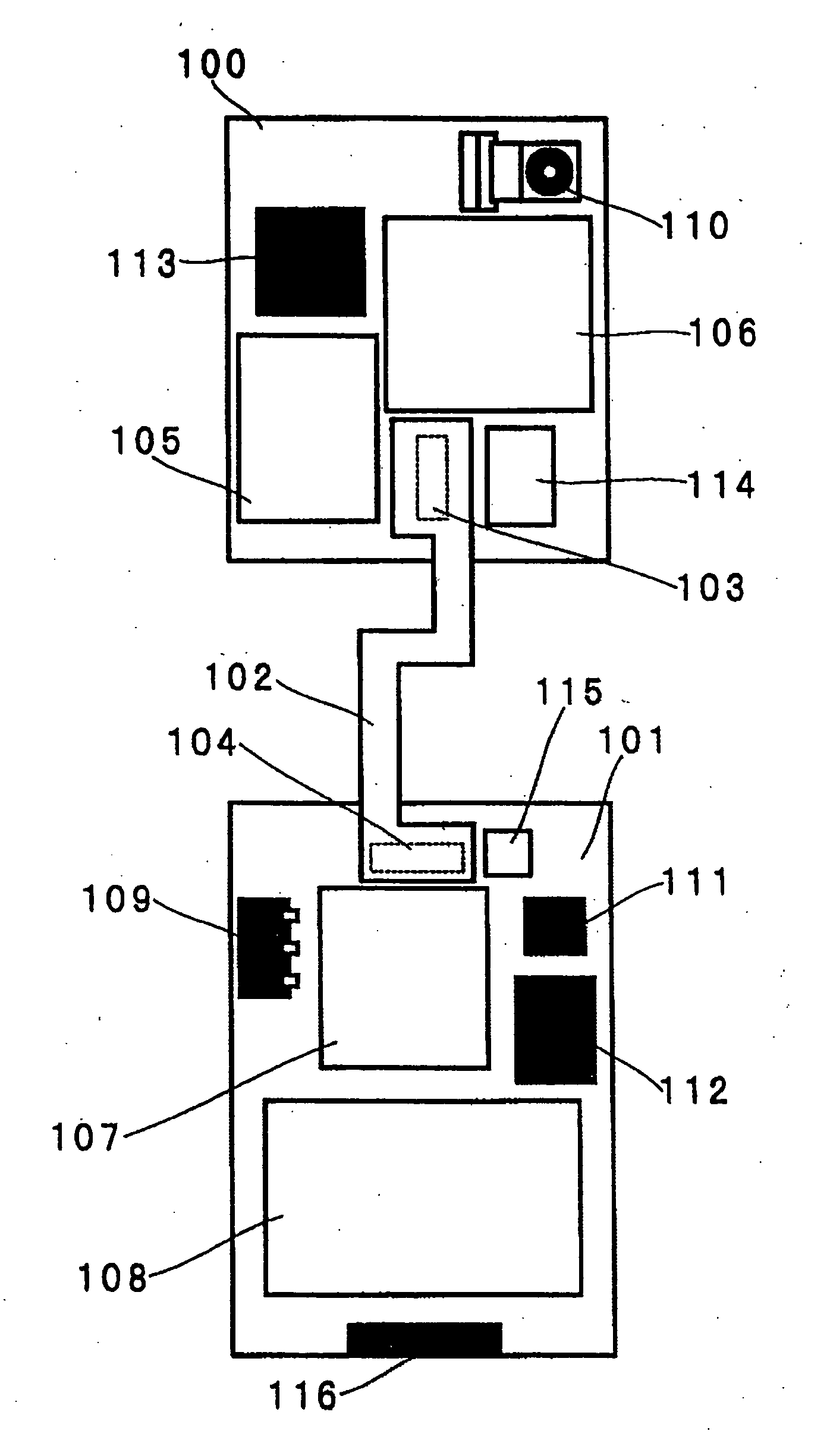
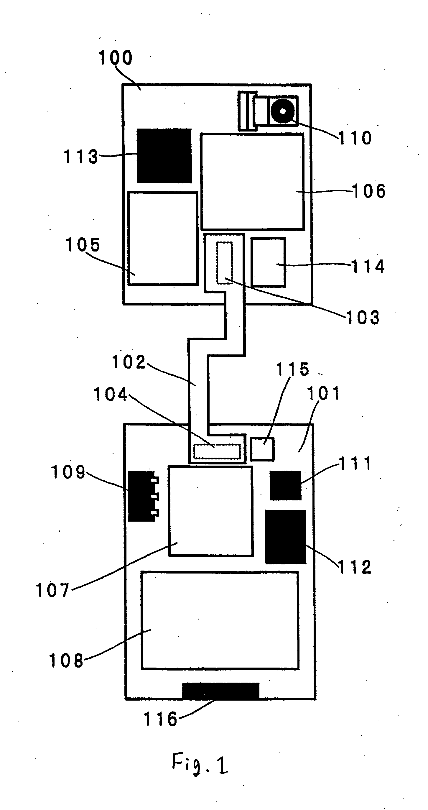
[0044] Referring now to FIG. 1, a flexible connection substrate according to the present invention is shown that includes first flexible substrate 102 that connects upper circuit substrate 100 and lower circuit substrate 101.

[0045] This flexible connection substrate is used in folding portable telephone 1 that is shown in FIG. 10. Folding portable telephone 1 includes upper case 11 and lower case 12 that are freely rotatably linked by hinge 13. Upper case 11 includes: display unit 14, speaker 15 for generating receiver sound and received sound; and upper circuit substrate 100 shown in FIG. 1 for these components. Lower case 12 includes: an operation unit that includes a plurality of keys 18 for input, a microphone 17 for collecting transmission sound, and lower circuit substrate 101 shown in FIG. 1 for these components. Upper circuit substrate 100 and lower circuit substrate 101 are interconnected by a flexible substrate. During use, folding portable telephone 1 is placed in an open...

second embodiment

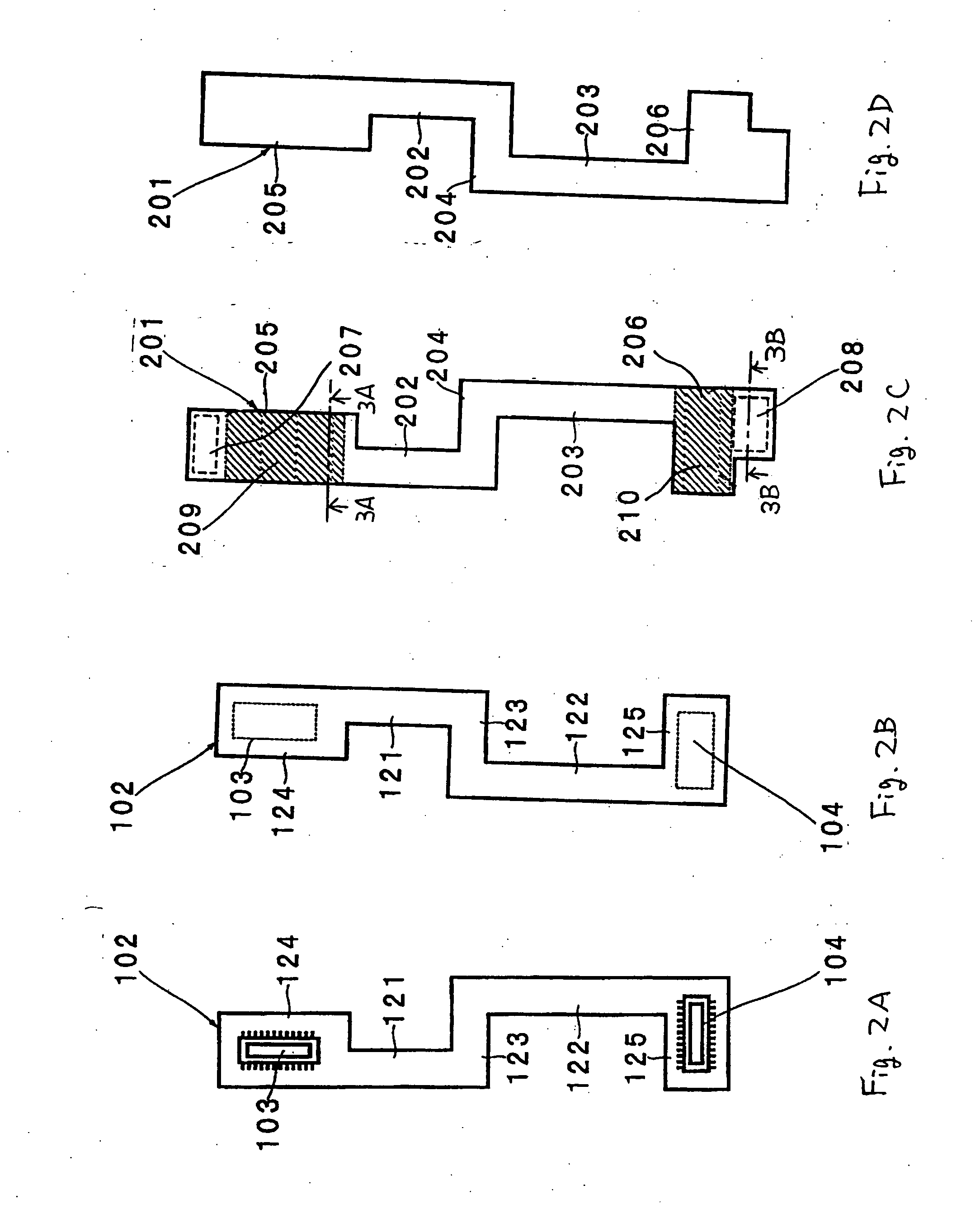
[0069] An example is next shown as the present invention in which second flexible substrate 201 that was described in FIG. 2 is caused to function as a shield of first flexible substrate 102. In first flexible substrate 102, signal lines such as a data bus or clock lines to an LCD pass from lower circuit substrate 101. It is well known that, when these signal lines are in operation, radiation noise that bring about a suppression of radio sensitivity is generated from the front surface of first flexible substrate 102.

[0070] In the prior art, a silver paste or film is printed on first flexible substrate 102 to thus shield noise. A silver paste or film hardens first flexible substrate 102 and can lead to line breaks caused by the opening and closing of the folding portable telephone. This paste or film is connected with GND portions on first flexible substrate 102 to connect with the GND of the upper and lower circuit substrates. In most cases, however, GND connection parts that are pr...


PUM


Abstract

A flexible connection substrate includes a first flexible substrate and a second flexible substrate. The first flexible substrate electrically connects first signal lines that are formed on a first circuit substrate to second signal lines that are formed on a second circuit substrate. The second flexible substrate is a flexible substrate for grounding, has a planar shape that is substantially the same as the first flexible substrate, and contains a conductive material throughout. The second flexible substrate connects to any of a plurality of grounding points that are formed on the first circuit substrate and any of a plurality of grounding points that are formed on the second circuit substrate. The first flexible substrate and the second flexible substrate are bonded to each other on one surface.

Description

BACKGROUND OF THE INVENTION [0001] 1. Field of the Invention [0002] The present invention relates to a flexible connection substrate and a folding electronic apparatus, and more particularly to a flexible connection substrate that is ideally used in a folding portable terminal such as a folding portable telephone, and to a folding electronic apparatus that uses this flexible connection substrate. [0003] 2. Description of the Related Art [0004] In recent years, portable telephones have come into wide use, and among these devices, folding portable telephones in particular are in wide use. A folding portable telephone includes an upper case and a lower case that are freely rotatably linked together by a hinge. The upper case has a display unit, a speaker for producing sound from the receiver and from received sound, and a first circuit substrate for these components. The lower case has an operation part that includes a plurality of keys for input, a microphone for collecting transmissi...

Claims


Application Information

Patent Timeline
Patent Type & Authority Applications(United States)
IPC IPC(8): H05K5/00H05K7/06
CPCH04M1/0216H05K1/0215H05K1/028H05K2201/10386H05K3/323H05K2201/0715H05K1/148
Inventor OOTANI, TAKUMI
Owner NEC CORP
Learn More