Method and apparatus for layered modulation

a layered modulation and apparatus technology, applied in the field of systems and methods for transmitting and receiving digital signals, can solve the problems of limited electromagnetic spectrum availability, inability to simply transmit enhanced or additional data at a new frequency, and difficulty in implementing either improvement in old systems and new services, so as to improve the carrier-to-noise ratio and improve the implementation of lm.

Inactive Publication Date: 2006-03-09
HUGHES ELECTRONICS
View PDF99 Cites 30 Cited by
  • Summary
  • Abstract
  • Description
  • Claims
  • Application Information

AI Technical Summary

Benefits of technology

[0016] Improvements to a layered modulation (LM) implementation are disclosed. The present invention relates to two implementations of LM, using single and multiple transponders per signal frequency, respectively. Layered hierarchical 8 PSK (H-8 PSK) is a special case of LM. By re-encoding the high-priority (HP) portion of an H-8 PSK signal, LM can improve carrier-to-noise ratio (CNR) of a H-8 PSK signal.
[0017] In addition, LM can be computer-simulated and a two-layered signal can be sequentially demodulated with a predicted CNR performance. An LM signal can be emulated using live signals for off-line processing. In addition, a signal processing apparatus can process in real time LM signals emulated from live satellite signals. Embodiments of the invention comprise systems and methods for simulating a layer-modulated signal, including a hierarchically modulated signal. Such systems and methods are useful in the development of layer modulated systems because they allow convenient testing of proposed implementations and adjustments to existing systems and provide performance indicators at low cost.

Problems solved by technology

However, it is more difficult to implement either improvement in old systems and new services when it is necessary to replace existing legacy hardware, such as transmitters and receivers.
In the realm of wireless communications, this principle is further highlighted by the limited availability of electromagnetic spectrum.
Thus, it is not possible (or at least not practical) to merely transmit enhanced or additional data at a new frequency.
Unfortunately, QPSK receivers cannot demodulate conventional 8 PSK or 16 QAM signals.

Method used


Image

  • Method and apparatus for layered modulation
  • Method and apparatus for layered modulation
  • Method and apparatus for layered modulation

Examples


Embodiment Construction

[0059] In the following description, reference is made to the accompanying drawings which form a part hereof, and which show, by way of illustration, several embodiments of the present invention. It is understood that other embodiments may be utilized and structural changes may be made without departing from the scope of the present invention.

Layered and Hierarchical Modulation / Demodulation

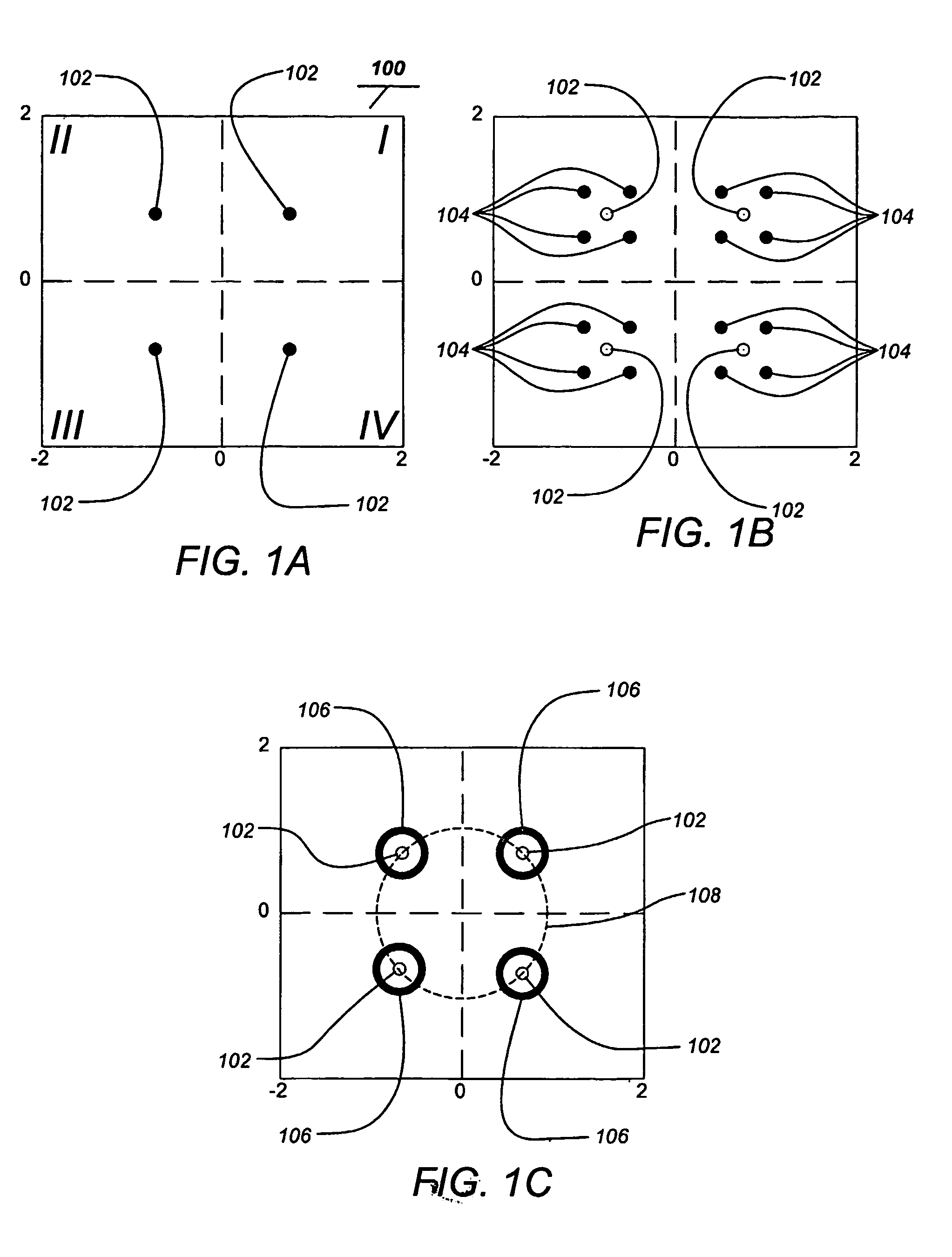
[0060]FIGS. 1A-1C illustrate the basic relationship of signal layers in a layered modulation transmission. FIG. 1A illustrates a first layer signal constellation 100 of a transmission signal showing the signal points or symbols 102. FIG. 1B illustrates the second layer signal constellation of symbols 104 over the first layer signal constellation 100 where the layers are coherent. FIG. 1C illustrates a second signal layer 106 of a second transmission layer over the first layer constellation where the layers may be non-coherent. The second layer 106 rotates about the first layer constellation 102 ...


PUM


Abstract

Improvements to a layered modulation (LM) implementation are disclosed. The present invention discloses two implementations of LM, using single and multiple transponders per signal frequency, respectively. Layered hierarchical 8PSK (H-8PSK) is a special case of LM. By re-encoding the high-priority (HP) portion of an H-8PSK signal, LM can improve carrier-to-noise ratio (CNR) of a H-8PSK signal. LM can be computer-simulated and a two-layered signal can be sequentially demodulated with a predicted CNR performance. An LM signal can be simulated 10 using live signals for off-line processing. In addition, a signal processing apparatus can process in real time LM signals emulated from live satellite signals.

Description

CROSS REFERENCE TO RELATED APPLICATIONS [0001] This application claims priority to the following U.S. Provisional Patent Application, which is incorporated by reference herein: [0002] U.S. Provisional Patent Application Ser. No. 60 / 393,437, filed on Jul. 3, 2002, and entitled “LAYERED MODULATION SIMULATION RESULTS”, by Ernest C. Chen et al. [0003] This applications is related to the following co-pending patent applications, both of which applications are hereby incorporated by reference: [0004] U.S. patent application Ser. No. 09 / 844,401, filed on Apr. 27, 2001, and entitled “LAYERED MODULATION FOR DIGITAL SIGNALS”, by Ernest C. Chen; [0005] U.S. patent application Ser. No. 10 / 068,039, filed on Feb. 5, 2002, and entitled “PREPROCESSING SIGNAL LAYERS IN A LAYERED MODULATION DIGITAL SIGNAL SYSTEM TO USE LEGACY RECEIVERS”, by Ernest C. Chen, et.al.; [0006] U.S. patent application Ser. No. 10 / 068,047, filed on Feb. 5, 2002, and entitled “DUAL LAYER SIGNAL PROCESSING IN A LAYERED MODULAT...

Claims


Application Information

Patent Timeline
Patent Type & Authority Applications(United States)
IPC IPC(8): H04L27/20H04L27/18H04L27/34
CPCH04L1/20H04L1/208H04L2001/0098H04L27/3488H04L27/183
Inventor CHEN, ERNESTCSANTORU, JOSEPH
Owner HUGHES ELECTRONICS
Why Eureka
Try Eureka