Shared frequency transmitter

a frequency transmitter and frequency technology, applied in the field of shared frequency transmitters, can solve the problem of 1/n-time decrease in frequency use efficiency per system, and achieve the effect of effectively removing interference between systems and improving frequency use efficiency

Inactive Publication Date: 2006-03-09
NTT DOCOMO INC
View PDF14 Cites 2 Cited by
  • Summary
  • Abstract
  • Description
  • Claims
  • Application Information

AI Technical Summary

Benefits of technology

[0011] Therefore, it is an object of the present invention to solve the problems in the conventional techniques and to provide a shared frequency transmitter that can effectively remove interference between systems and greatly improve frequency use efficiency under the circumstance where transmitters and receivers of the plural systems sharing the same frequency coexist.
[0031] With the aforementioned aspects of the invention, since exchanging of information is performed between transmitters of the plural systems and various interference cancellation techniques become available on the transmission side based on the acquired information, it is possible to effectively cancel interference between systems and remarkably improve frequency use efficiency.

Problems solved by technology

By the way, a problem that occurs when the plural systems share the same frequency is interference between systems.
However, according to the aforementioned prior art in which interference between systems is prevented by using protocols such as CSMA-CA, the communications between systems is performed according to a time division scheme, so there is a problem in that frequency use efficiency per system decreases 1 / N times with respect to the case of only one system at a time allocated for a frequency band. FIG. 3 is a diagram showing a frequency use situation by each system on a time axis.

Method used


Image

  • Shared frequency transmitter
  • Shared frequency transmitter
  • Shared frequency transmitter

Examples


first embodiment

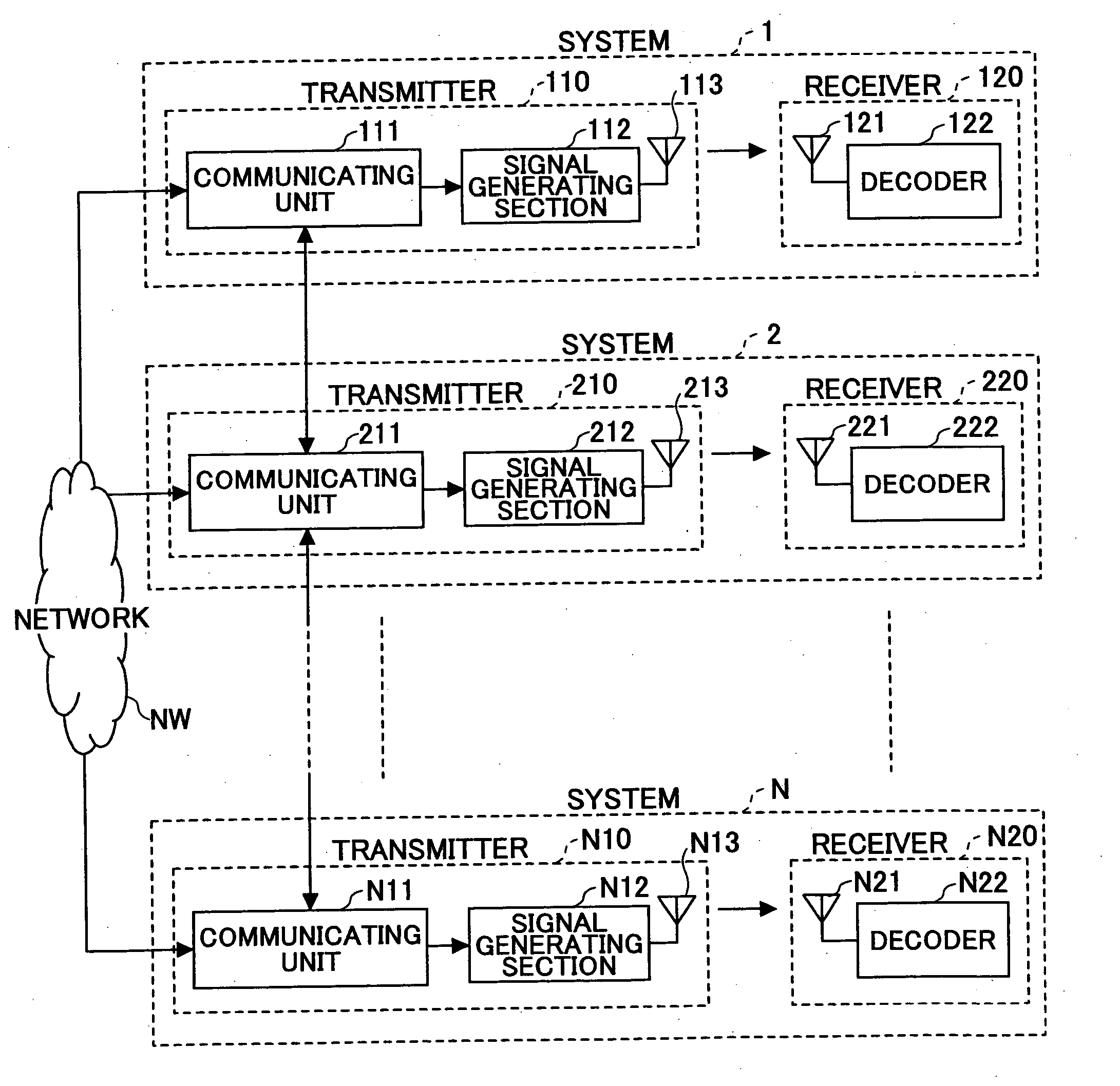
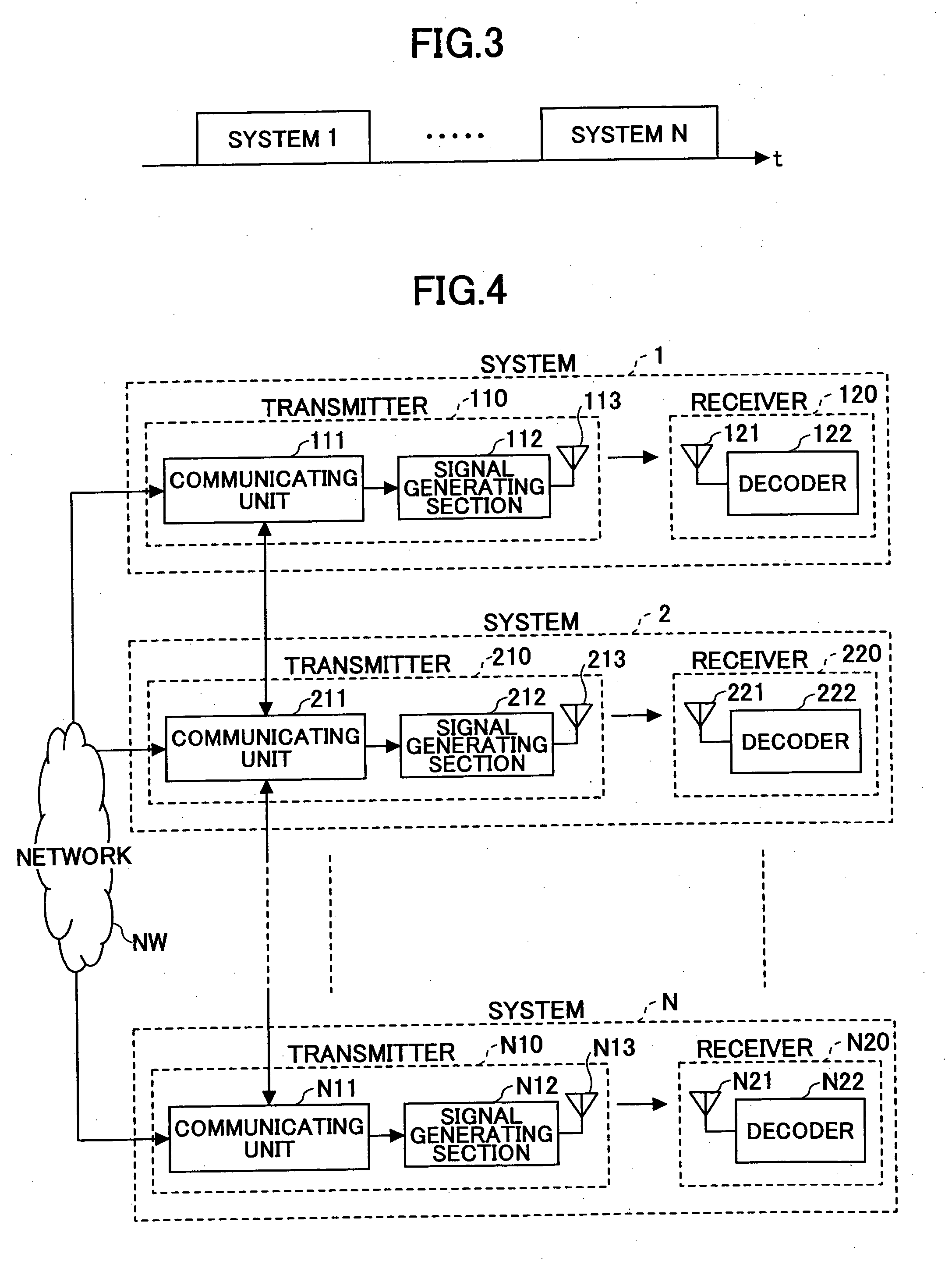
[0052]FIG. 4 is a diagram showing an example of a configuration of transmitters and receivers under the circumstance where plural systems coexist, according to the present invention. In FIG. 4, systems 1, 2 . . . N indicate wireless communication systems provided by different wireless LAN enterprises using the same frequency band. The respective systems 1, 2 . . . N are provided with transmitters 110, 210 . . . N10 connected to a wired network NW such as the Internet, and receivers 120, 220 . . . N20 opposed to these transmitters, respectively. The respective transmitters 110, 210 . . . N10 are provided with communicating units 111, 211 . . . N11 having functions of detecting (searching for) peripheral transmitters in a peripheral area and communicating with the detected peripheral transmitters to exchange information, signal generating units 112, 212 . . . N12 configured to generate transmit signals by applying an interference cancellation technique based on the information obtaine...

second embodiment

[0079]FIG. 11 is a diagram of the configuration according to the present invention, in which radio communication such as Bluetooth communication is used as a communicating function of the communicating units 111, 211 . . . of the transmitters 110, 210 . . . of the systems 1, 2 . . . . It is noted that the configuration of the receiver is omitted in the drawing; however, the remaining part is the same as shown in FIG. 4.

[0080] The second embodiment is suited for the case where the transmitters 110, 210 . . . of the systems 1, 2 . . . are located at a short distance from each other. It is noted that infrared communication other than Bluetooth communication can be used.

third embodiment

[0081]FIG. 12 is a diagram of the configuration according to the present invention, in which wired communication via a router R is used as a communicating function of the communicating units 111, 211 . . . of the transmitters 110, 210 . . . of the systems 1, 2 . . . . It is noted that the configuration of the receiver is omitted in the drawing; however, the remaining part is the same as shown in FIG. 4.

[0082] In the third embodiment, the transmitters 110, 210 . . . of the systems 1, 2 . . . perform packet communication by wired communication link. Thus, the third embodiment is applicable in the case where the transmitters 110, 210 . . . of the systems 1, 2 . . . are not located at a short distance from each other.


PUM


Abstract

A shared frequency transmitter for use in a network environment where transmitters and receivers of plural radio communication systems in which the same frequency is used exist is disclosed. The shared frequency transmitter includes (a) a communicating unit configured to detect peripheral transmitters existing in a peripheral area, and to exchange information with the detected peripheral transmitters; and (b) a signal generating unit configured to generate a transmit signal by applying an interference cancellation technique based on the information obtained through the exchange of information.

Description

FIELD OF THE INVENTION [0001] The present invention generally relates to a shared frequency transmitter used in a network environment where plural radio communication systems are mixed. BACKGROUND OF THE INVENTION [0002] With the recent explosive increase in demand for radio communications, the variety of radio communication methods as well as the number of radio communication enterprises have increased. In addition, broadening the frequency band for a wireless communication systems is being promoted correspondingly, whereby the frequency band available for radio communication dries up. [0003] Considering this trend, recently a solution in which plural systems share the same frequency band has been proposed and reduced to practice. For example, there is a frequency band as referred to as an ISM (Industrial Scientific Medical) band. As for this frequency band, a radio license is unnecessary, and many radio communication enterprises such as wireless LAN (Local Area Network) enterprise...

Claims


Application Information

Patent Timeline
Patent Type & Authority Applications(United States)
IPC IPC(8): H04B7/06H04B7/02
CPCH04B1/1027H04W16/14H04B15/02H04B1/02
Inventor ABE, TETSUSHISHI, HUIASAI, TAKAHIROYOSHINO, HITOSHI
Owner NTT DOCOMO INC
Why Eureka
Try Eureka