
Loudspeaker with variable radiation pattern

a loudspeaker and radiation pattern technology, applied in the direction of transducer types, frequency/directions obtaining arrangements, loudspeaker spatial/constructional arrangements, etc., can solve the problem of difficult or impossible for the listener to localize any of the acoustic signals, delay circuitry (typically requiring a separate component) is relatively expensive and noisy, and the listener is difficult or impossible to localize the sound

Inactive Publication Date: 2006-03-09
LEVITSKY IGOR
View PDF4 Cites 38 Cited by
  • Summary
  • Abstract
  • Description
  • Claims
  • Application Information

AI Technical Summary

Benefits of technology

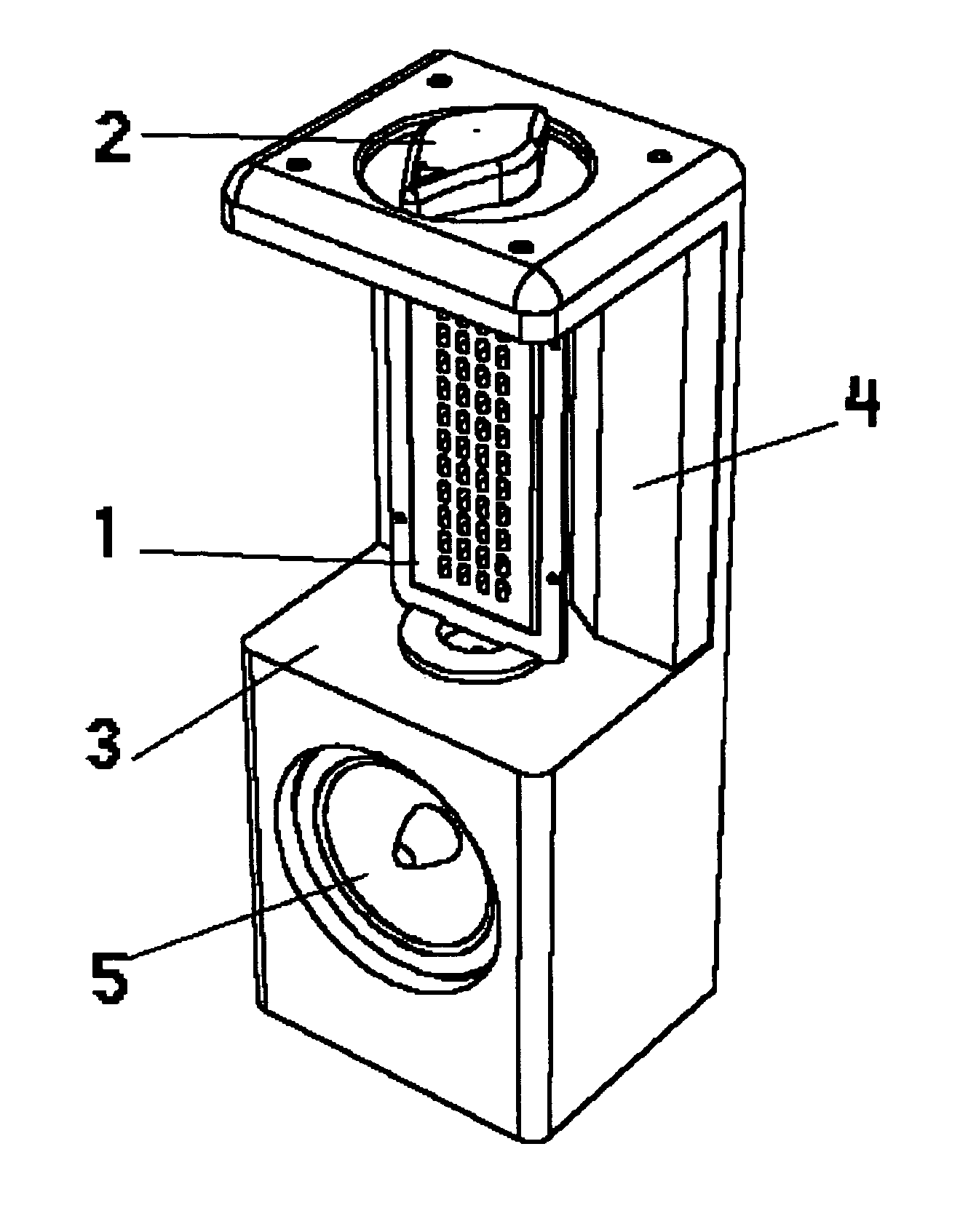
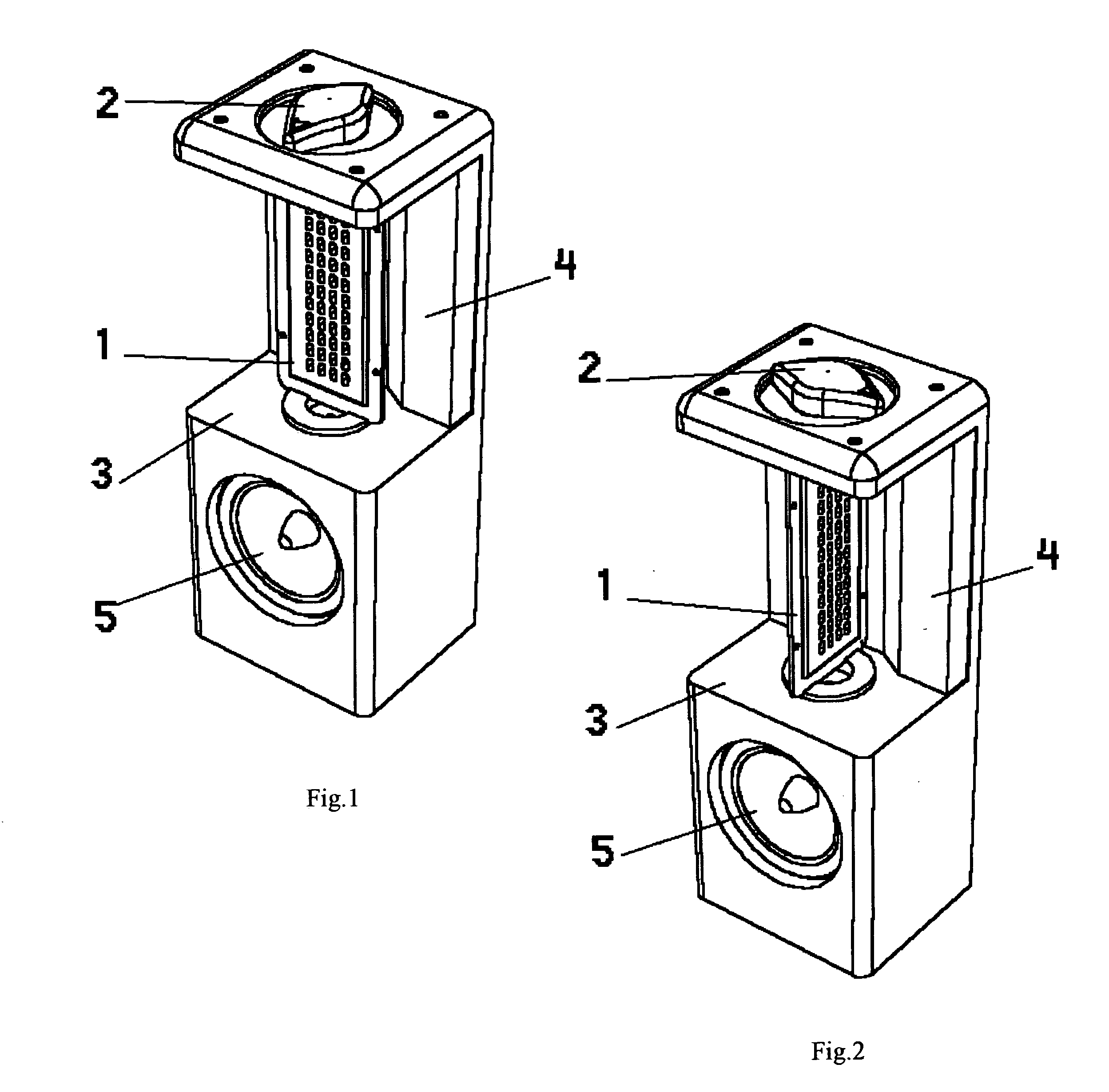
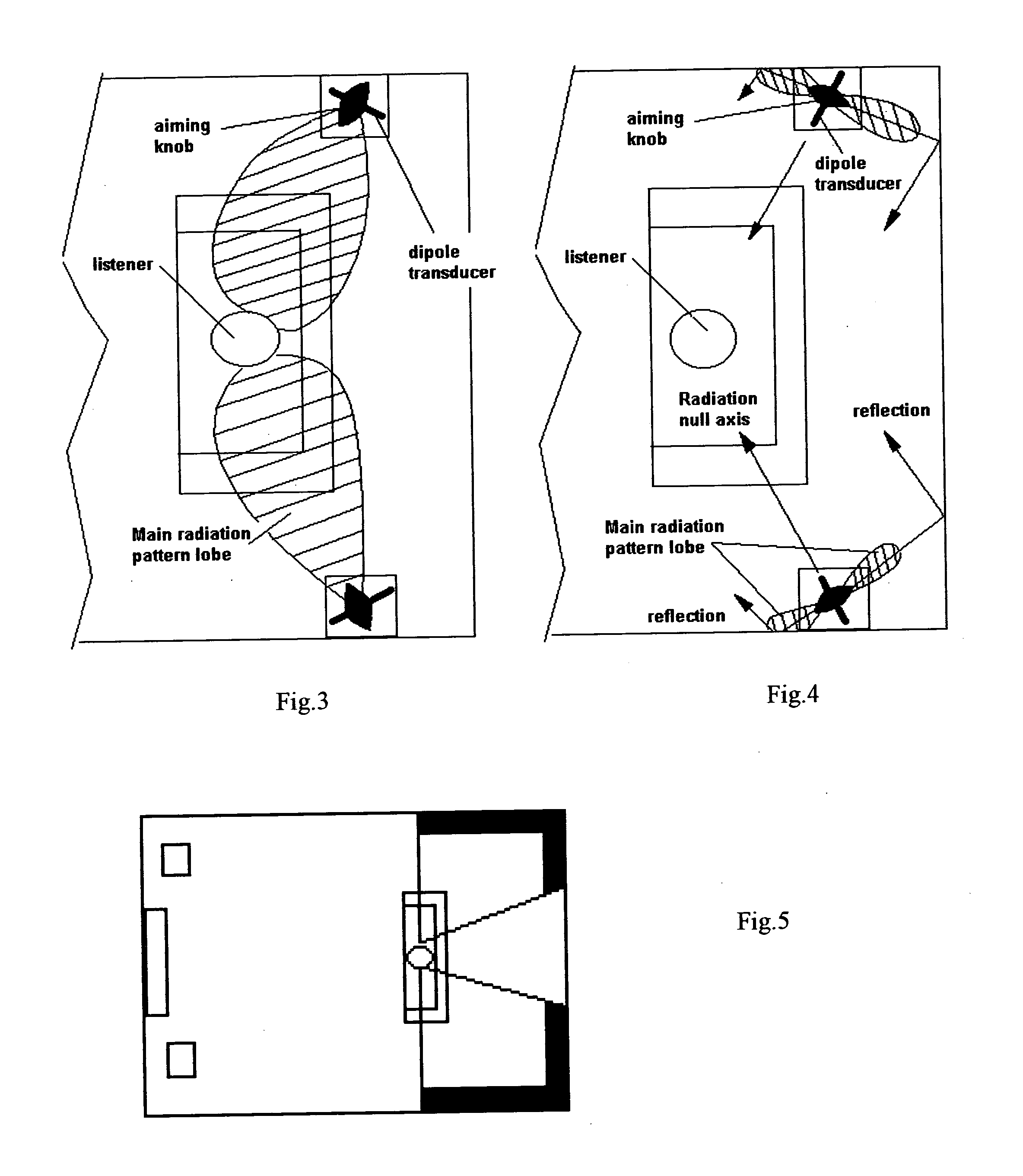
[0025] In the first aspect of the invention the aiming knob provides the rotation of the dipole transducer and helps a user to determine the direction of the main radiation pattern lobe without actually seeing the transducer's or the knob's position. The aiming knob has elongated and pointed shape so that it points in the direction of direct sound radiation in the plane of rotation.
[0027] In the third aspect of the invention the ability to rotate and aim the dipole transducer in horizontal plane provides flexibility in the loudspeaker installation. If the loudspeaker is used for a surround sound applications, it can be installed almost anywhere in the rear part of the room behind the listener where the speakers can deliver acceptable performance. The location is not limited by loudspeaker's sound dispersion characteristics and provides more freedom for user preferences in room design and convenience.

Problems solved by technology

Unfortunately, a problem with conventional sound reproduction systems is the tendency of the sound to be localized by the listener at the loudspeakers, or imaged at a point relative to the loudspeakers.
While this approach has achieved some success in producing a “surround sound” effect, it possesses a number of inherent disadvantages: not only is the delay circuitry (which typically requires housing in a separate component) both relatively expensive and noisy, but the approach also ordinarily employs two dedicated “surround sound” speakers, in addition to the conventional, non-delayed speakers of the stereo system.
The most significant of these lies in the very fact the system is intended to prevent the listener from localizing sound for the whole of both channels of the stereo system; in other words, this arrangement renders it difficult or impossible for the listener to localize any of the acoustical signals which are reproduced by the system, regardless of whether those signals were originally recorded as direct path signals or indirect path signals.
This is undesirable in that it consequently makes it impossible for the listener to localize those sources (e.g., a singer or particular instrument) where a degree of localization is desirable.
A problem with these audio and video systems is that the surround sound loudspeakers in these systems are either dipolar or bipolar and are placed external to the wall surfaces of a room containing the system.
As a result, mass consumer acceptance of some of these types of systems is relatively low because the surround loudspeaker are bulky, visually unappealing and tend to force a consumer to utilize the room exclusively for a cinema home theater system.
However, it is difficult to produce an ambient sound field equivalent to the external surround sound loudspeakers with a sound reproduction system that is imbedded and flush within the wall and ceiling surfaces because the dispersion from its locations within walls are obscured by the wall and ceiling surfaces.
Typically, unless the loudspeaker is capable of producing an angled pattern for the sound, the loudspeaker will be obstructed and will not be able to create the type of sound stage that is desirable for accurate sound reproduction within the home theater system.
An additional problem with these audio and video systems is that typically rooms are arranged differently from home-to-home.
Still another problem is that generally audio and video systems that are optimized for a cinema environment are different than audio systems that are optimized for a music listening environment.

Method used


Image

  • Loudspeaker with variable radiation pattern
  • Loudspeaker with variable radiation pattern
  • Loudspeaker with variable radiation pattern

Examples


Embodiment Construction

[0035] The current situation with rear channel loudspeakers in home theater and multi-channel audio has a confusing element for a user. Surround sound audio in its recent reincarnation was first boosted by consumer version of Dolby Surround systems for movies and special THX processing algorithm developed for consumer home theater systems. The idea is to transfer the movie theater audio experience into a home environment. According to THX recommendations the home theater system should have at least 5 audio channels, frontal left, frontal center, frontal right and two surround sound channels located to the rear of the listening position. While frontal channels specify mostly direct radiating loudspeakers, the rear channels according THX should produce predominantly diffuse sound. Dipole speakers aimed at the listener with their “nulls” are preferred in order to recreate the ambient sound field and envelopment as intended by movie mix producers. With advent of multi-channel music-only...


PUM


Abstract

The invention is a loudspeaker for use in home theater or multi-channel sound systems that includes an enclosure, a wideband transducer, a sound absorbing pad and an aiming knob. The wideband transducer is rotatably mounted in the enclosure so that the wideband transducer can be rotated around its vertical axis and an aiming knob mechanically coupled to the wideband transducer. The wideband transducer has a front side and a rear side open so that said wideband transducer operates as a dipole transducer. The aiming knob controls the rotation angle of the dipole transducer. The loudspeaker uses the dipole transducer to create either a diffuse field or direct radiating surround sound.

Description

[0001] This is a continuation-in part of a provisional application, entitled Loudspeaker with Variable Radiation Pattern, filed by Igor Levitsky on Sep. 3, 2003 under Serial No. ______.BACKGROUND OF THE INVENTION [0002] Multiple channel sound reproduction systems which include a surround-sound channel (often referred to in the past as an “ambience” or “special-effects” channel) in addition to left and right (and optimally, center) sound channels are now relatively common in motion picture theaters and are becoming more and more common in the homes of consumers. A driving force behind the proliferation of such systems in consumers' homes is the widespread availability of surround-sound home video software, mainly surround-sound motion pictures (movies) made for theatrical release and subsequently transferred to home video media, such as videocassettes, videodiscs and either broadcast or cable television. When a motion picture is transferred from film to home video media, the soundtra...

Claims


Application Information

Patent Timeline
Patent Type & Authority Applications(United States)
IPC IPC(8): H04R5/02H04R1/02H04R9/06
CPCH04R1/26H04R1/288H04S3/00H04R2440/07H04R1/345
Inventor LEVITSKY, IGOR
Owner LEVITSKY IGOR
Learn More