

Solar cell interconnect
a technology of solar cells and interconnects, applied in the field of solar cells, can solve the problems of cell failure, thermal mismatch between the conductors of the cell interconnect and the cell substrate, breakage of the silicon cell or the conductor, etc., and achieve the effects of long-term dependability, acceptable thermal and electrical performance, and efficient manufacturing
- Summary
- Abstract
- Description
- Claims
- Application Information
AI Technical Summary
Benefits of technology
Problems solved by technology
Method used
Image

Examples
Embodiment Construction
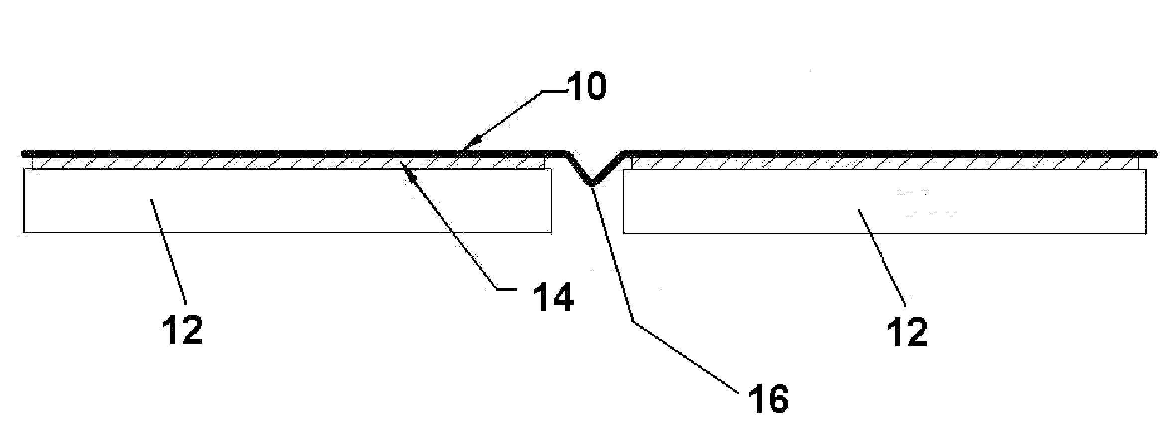
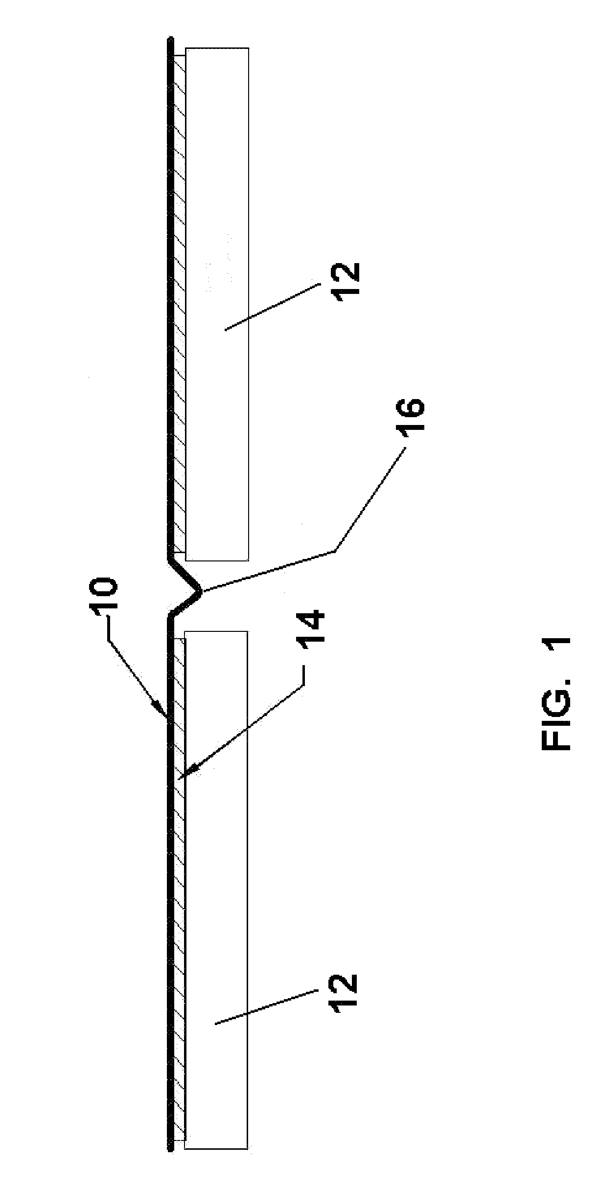
[0016]Referring to FIG. 1, there is shown a solar cell interconnect 10 electrically connected in series to a plurality of solar cells 12 at a solder connection at the cell substrate 14. The interconnect 10 is elongated in strip form and includes an expansion joint 16 between adjacent cells 12.
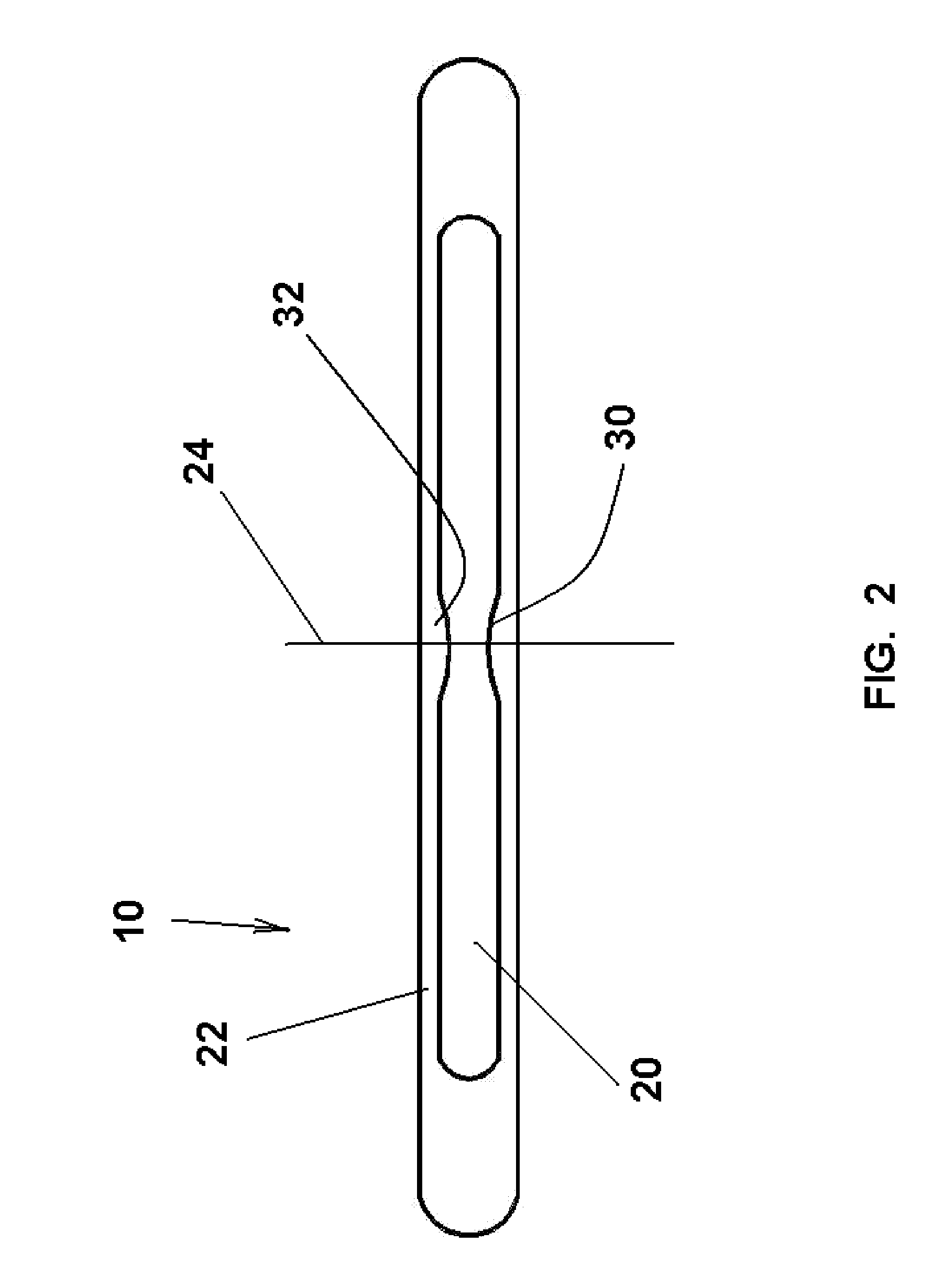
[0017]Referring to FIG. 2, the interconnect 10 comprises a core 20 of a first material metallurgically clad with a covering 22 of a second material. The covering is a copper based material, preferably copper or a copper alloy. The core is a nickel / iron based material, preferably a nickel alloy with iron with nickel in the range of about 30-60% by weight. Suitable nickel alloys include Alloy 42, Alloy 36 (INVAR), and Alloy 52.
[0018]The core 20 is generally rectangular in cross section. The covering 22 is generally symmetrical with the core 20 about a vertical longitudinal plane 24, with the lateral sides of greater width than the top and bottom thicknesses.
[0019]The core 20 includes opposed long...
PUM
| Property | Measurement | Unit |
|---|---|---|
| Fraction | aaaaa | aaaaa |
| Fraction | aaaaa | aaaaa |
| Fraction | aaaaa | aaaaa |
Abstract
Description
Claims
Application Information