
Method and apparatus for transmitting a coded video signal

a video signal and coded technology, applied in the field of methods and apparatus for transmitting a coded video signal, can solve problems such as difficulty in adjusting the bit rate of jpeg2k, and inability to achieve the effect of adjusting the bit ra

Inactive Publication Date: 2006-03-09
SONY CORP +1
View PDF9 Cites 123 Cited by
  • Summary
  • Abstract
  • Description
  • Claims
  • Application Information

AI Technical Summary

Benefits of technology

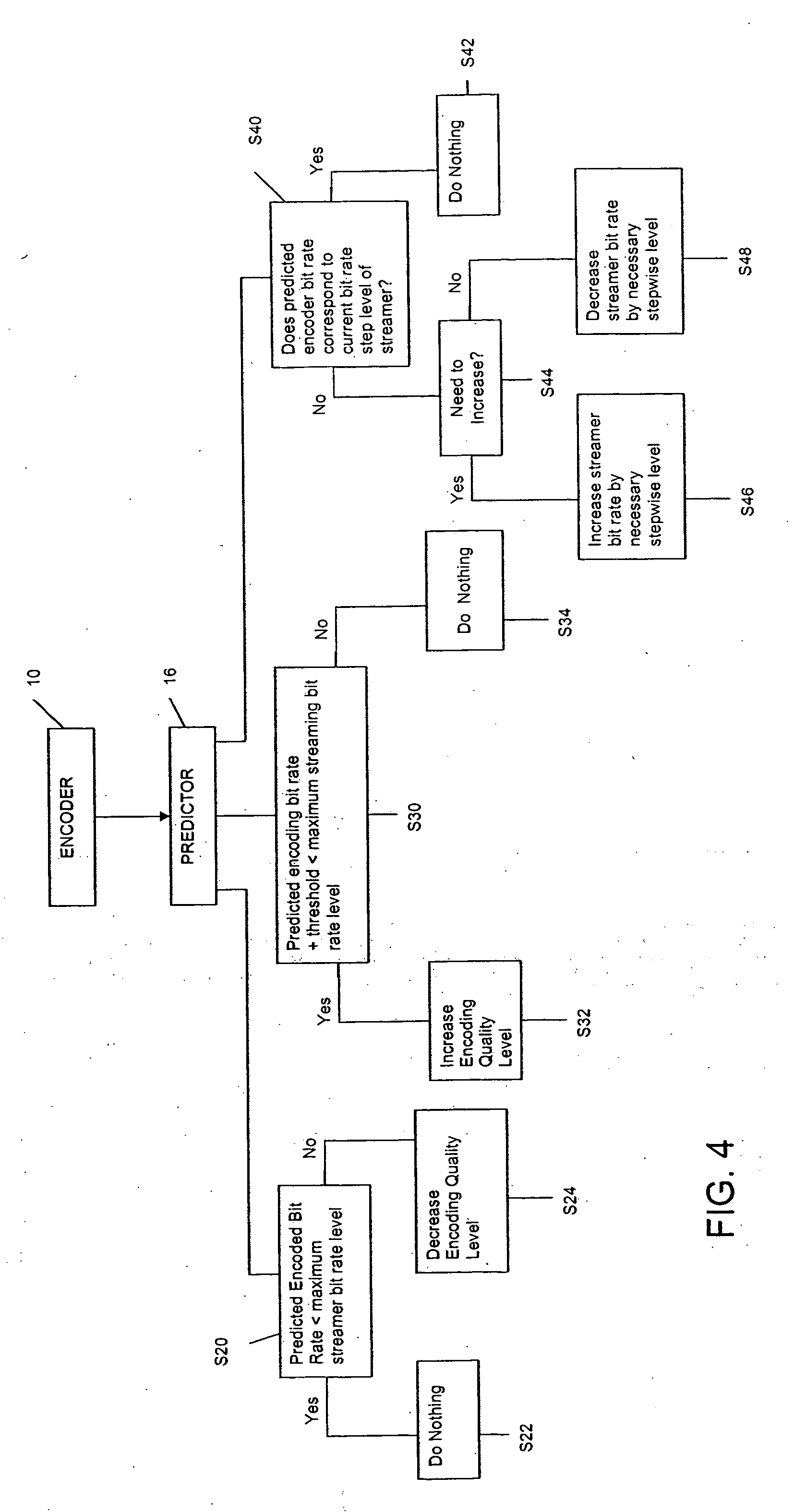
[0010] With this relationship, the size of the buffer can be enlarged by an amount equal to the momentary encoded bit rate minus the momentary streaming bit rate when the streaming bit rate is set to a maximum value such that further increase would result in a buffer overflow condition.
[0011] According to one embodiment of the basic invention, the method further includes defining a set of strip-wise constant bit rate streaming levels; and the bit rate is adjusted by raising and lowering the streaming bit rate level proportionately to an increase or decrease of the predicted encoded bit rate level, using the set of step-wise streaming levels.
[0012] According to a further embodiment of the basic invention, the method further includes providing the encoding algorithm with a defined set of quality levels proportional to the encoding bit rate; and the bit rate is adjusted by decreasing the encoding quality level, and thus the encoding bit rate, if the predicted encoding bit rate is greater than a maximum streaming bit rate level. Additionally, the bit rate may be adjusting by increa

Problems solved by technology

However, this impressive compression capacity comes as a trade-off of implementation complexity.
However, this variable bit rate poses a challenge in a streaming environment of a data network, e.g., the internet streaming environment.
In the above environments, the variable bit rate of JPEG2K poses a problem.

Method used


Image

  • Method and apparatus for transmitting a coded video signal
  • Method and apparatus for transmitting a coded video signal
  • Method and apparatus for transmitting a coded video signal

Examples


Embodiment Construction

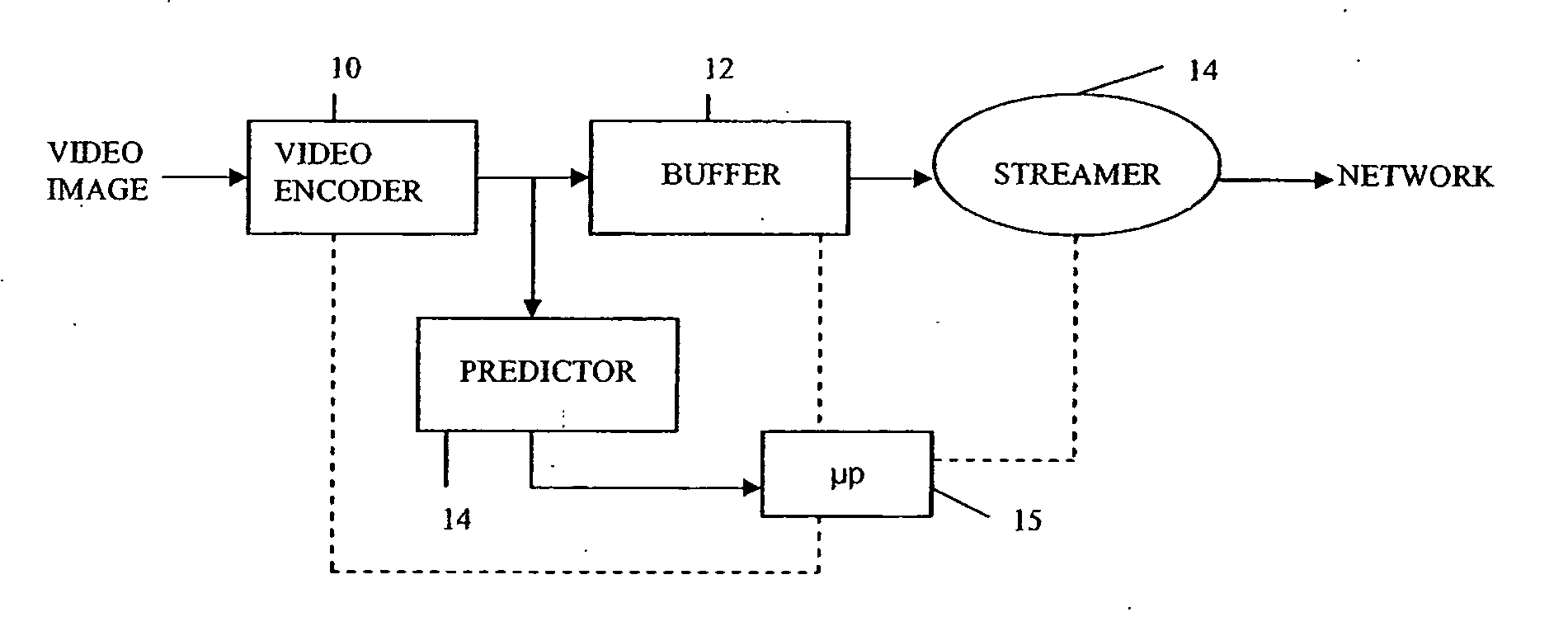
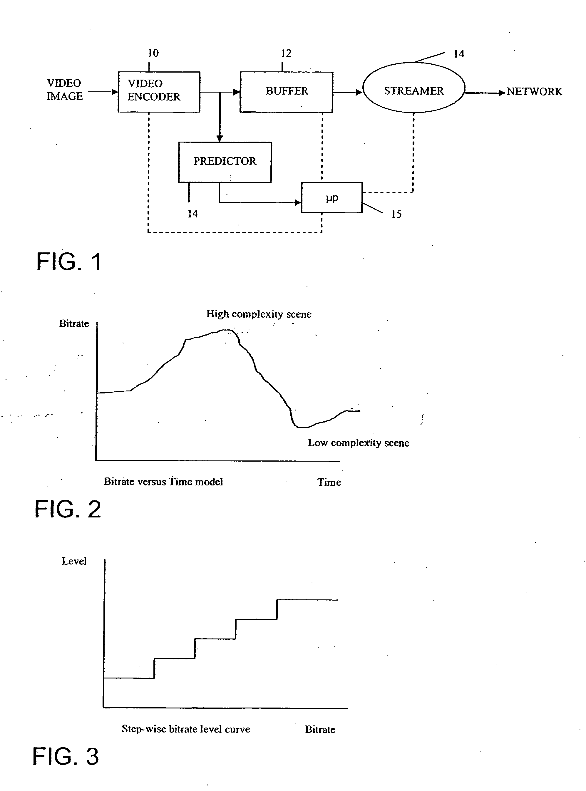
[0018] Referring now to FIG. 1, there is shown the basic streamer model for the arrangement according to the invention for the transmission of the encoded video signal.

[0019] As shown, the video image is sent to a video encoder 10, which digitally encodes the video image using an algorithm having a variable bit rate, for example, a JPEG 2K encoder, and has a set of defined quality levels, for example, super low, low, medium, high, super high. These quality levels will be proportional to the encoding rate. The output from the video encoder 10 is, as shown, fed to a buffer 12 which is of known size, and which operates in a conventional manner as a first-in, first out buffer, and from the buffer 12 to a streamer 14, which extracts the data from the buffer 12 and produces a data stream at a streamer bit rate dictated by the network, e.g., the internet. The output of the streamer 14 is then fed as the stream of data to the network at the streamer bit rate.

[0020] According to the invent...


PUM


Abstract

A method and apparatus for transmitting a digitally encoded video image in real time via a data network wherein the video image is digitally encoded using a compression algorithm having a variable bit rate, e.g., JPEG2K, to provide an encoded data stream, the encoded data stream is fed into a buffer of known size, and the data is read from the buffer via a streamer with a controllable bit rate to provide a bit stream at a desired stream bit rate for transmission via the network. The bit rate of the encoded data stream from the encoder is monitored by a predictor and predicts a future bit rate of the encoded data stream; and, the bit rate of at least one of the encoder and the streamer is adjusted to provide the desired streaming bit rate.

Description

BACKGROUND OF THE INVENTION [0001] The present invention relates to a method and apparatus for transmitting a coded video signal in real time via a data network. More particularly, the present invention relates to a method and apparatus for transmitting an encoded digital video signal in real time via a data network wherein the encoding of the video image involves using a compression algorithm having a variable mid-rate to provide the digitally encoded data stream. [0002] Since the mid-'90s, JPEG (Joint Photographic Export Group) is a standard that has been very widely used in the compression of digital still images. However, and more recently, the study of wavelets, particularly wavelet transformers, has led to a new compression method that is called JPEG 2000 or JPEG2K and variations thereof. Unlike the original JPEG algorithm, the JPEG 2000 or JPEG2K algorithm can be applied to both still images and to motion video. [0003] JPEG2K allows for up to a 200-1 compression ratio with ve...

Claims


Application Information

Patent Timeline
IPC IPC(8): G06K9/36
CPCH04N21/23406H04N21/44004H04N19/149H04N21/658H04N19/503H04N21/6377
Inventor GUNATILAKE, PRIYAN
Owner SONY CORP
Learn More