
Optical communication network system, wavelength routing apparatus, communication node, optical path managing method for use in optical cross connect apparatus, and apparatus for that method

a technology of optical communication network and wavelength routing, applied in the direction of data switching network, multiplex communication, wavelength-division multiplex system, etc., can solve the problems of increasing transmission rate and increasing, increasing transmission rate, and achieving flexibility and expansion. , the effect of increasing the transmission capacity

Inactive Publication Date: 2006-03-09
NIPPON TELEGRAPH & TELEPHONE CORP
View PDF1 Cites 19 Cited by
  • Summary
  • Abstract
  • Description
  • Claims
  • Application Information

AI Technical Summary

Benefits of technology

[0033] The present invention has been conceived in the light of the above-described problems, and its object is to provide an optical communication network system and a wavelength-routing device and a communication node therefor, which can easily increase the number of optical paths between the communication nodes and are capable of increasing the transmission capacity, and which excel in flexibility and expandability.

Problems solved by technology

In recent years, communication traffic is constantly increasing along with the spread of broadband service and the increase in the utilization of information interchange by companies which take advantage of the internet, and demand for increase of the capacity and the rate of communication networks is unrelenting.
Nowadays, routing of data packets is performed electrically by converting the optical signal to an electrical signal, but, along with increases in the transmission rate and increases in capacity, the routing by electrical processing of a high volume signal will reach a limit in the near future.
However, with the above-described conventional optical communication network system based upon wavelength-routing of the arrayed-waveguide grating 110, although the communication node 100-1 can transmit information to the communication node 100-3 with an optical signal of wavelength λ3, it is difficult to increase the transmission capacity from the communication node 100-1 to the communication node 100-3 above the transmission capacity of an optical signal of one wavelength.
In this manner, with an optical communication network system of the conventional structure which is based upon wavelength-routing by an arrayed-waveguide grating 110, there is the problematical aspect that it is extremely difficult to increase the transmission capacity by increasing the number of optical paths between the communication nodes.
Furthermore, with the method of establishing an optical path between communication nodes for each wavelength-band, the number of communication nodes to which some communication node can transmit information is limited to the number of wavelength-bands, and there is the problem that, if the number of communication nodes exceeds the number of the wavelength-bands, then a combination of the communication nodes is created in which information is not delivered unless it is transmitted via other communication nodes.
However, due to the condition that optical signals of the same wavelength are not outputted from the same output optical fiber, the optical paths between the input optical fibers and the output optical fibers cannot be set freely.

Method used


Image

  • Optical communication network system, wavelength routing apparatus, communication node, optical path managing method for use in optical cross connect apparatus, and apparatus for that method
  • Optical communication network system, wavelength routing apparatus, communication node, optical path managing method for use in optical cross connect apparatus, and apparatus for that method
  • Optical communication network system, wavelength routing apparatus, communication node, optical path managing method for use in optical cross connect apparatus, and apparatus for that method

Examples


first embodiment

The First Embodiment

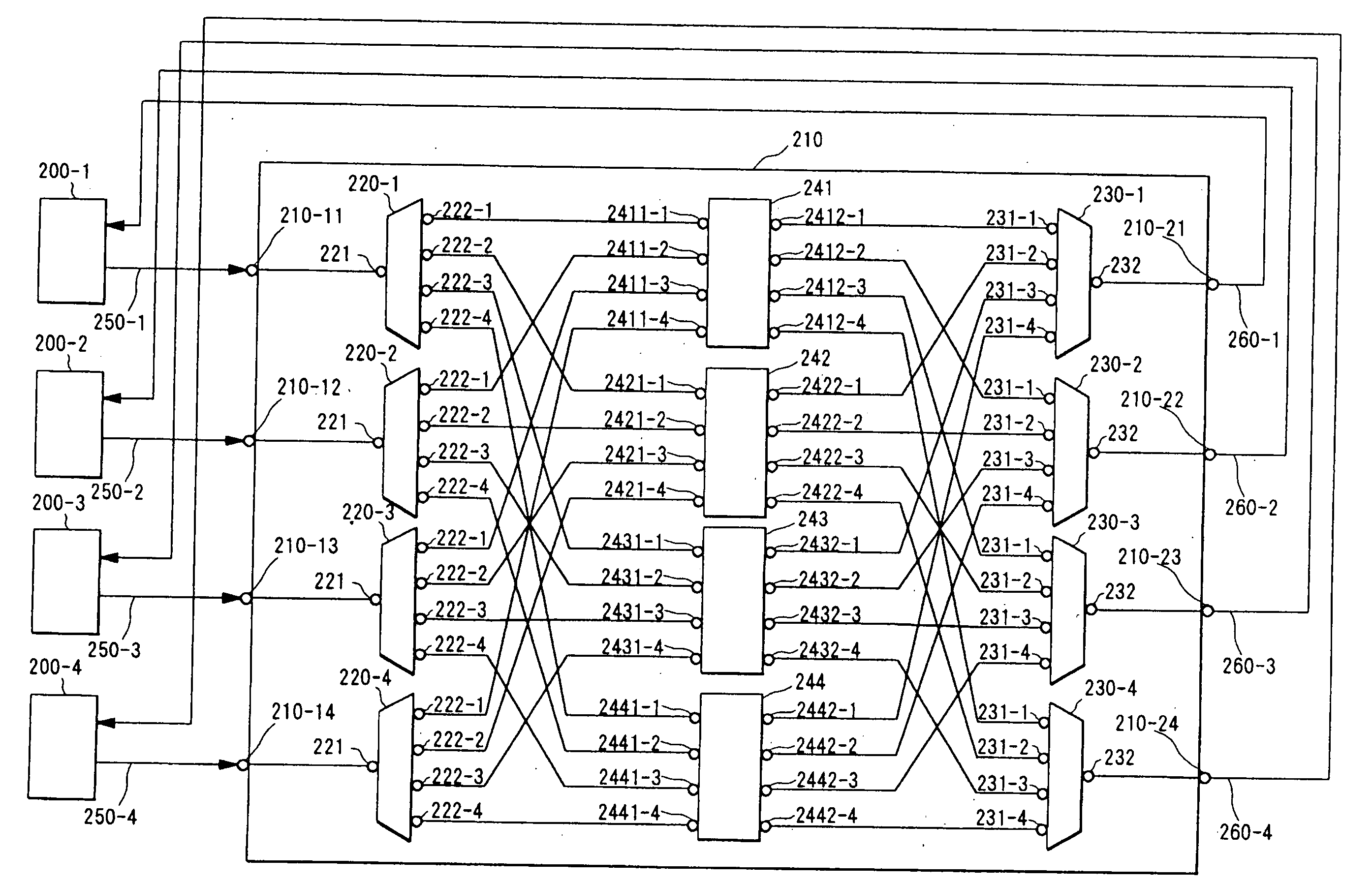
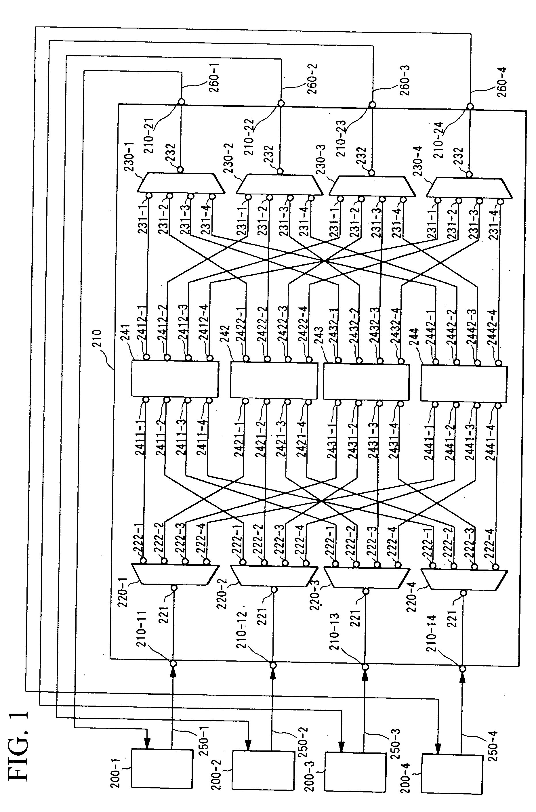
[0095]FIG. 1 is a structural figure showing the optical communication network system of the first embodiment according to the present invention. In FIG. 1, 200-1 through 200-4 are communication nodes, 210 is a wavelength-routing device, and 250-1 through 250-4 and 260-1 through 260-4 are optical transmission lines (optical fibers) which connect the communication nodes 200-1 through 200-4 and the wavelength-routing device 210.

[0096] Furthermore, the wavelength-routing device 210 comprises four device input ports 210-11 through 210-14 and four device output ports 210-21 through 210-24, wavelength-band demultiplexers 220-1 through 220-4, wavelength-band multiplexers 230-1 through 230-4, and 4×4 arrayed-waveguide gratings 241 through 244.

[0097] The communication node 200-1, along with being connected to the first device input port 210-11 of the wavelength-routing device 210 via the optical transmission line 250-1, is also connected to the first device output port 2...

second embodiment

The Second Embodiment

[0148] Next, the second embodiment according to the present invention will be explained.

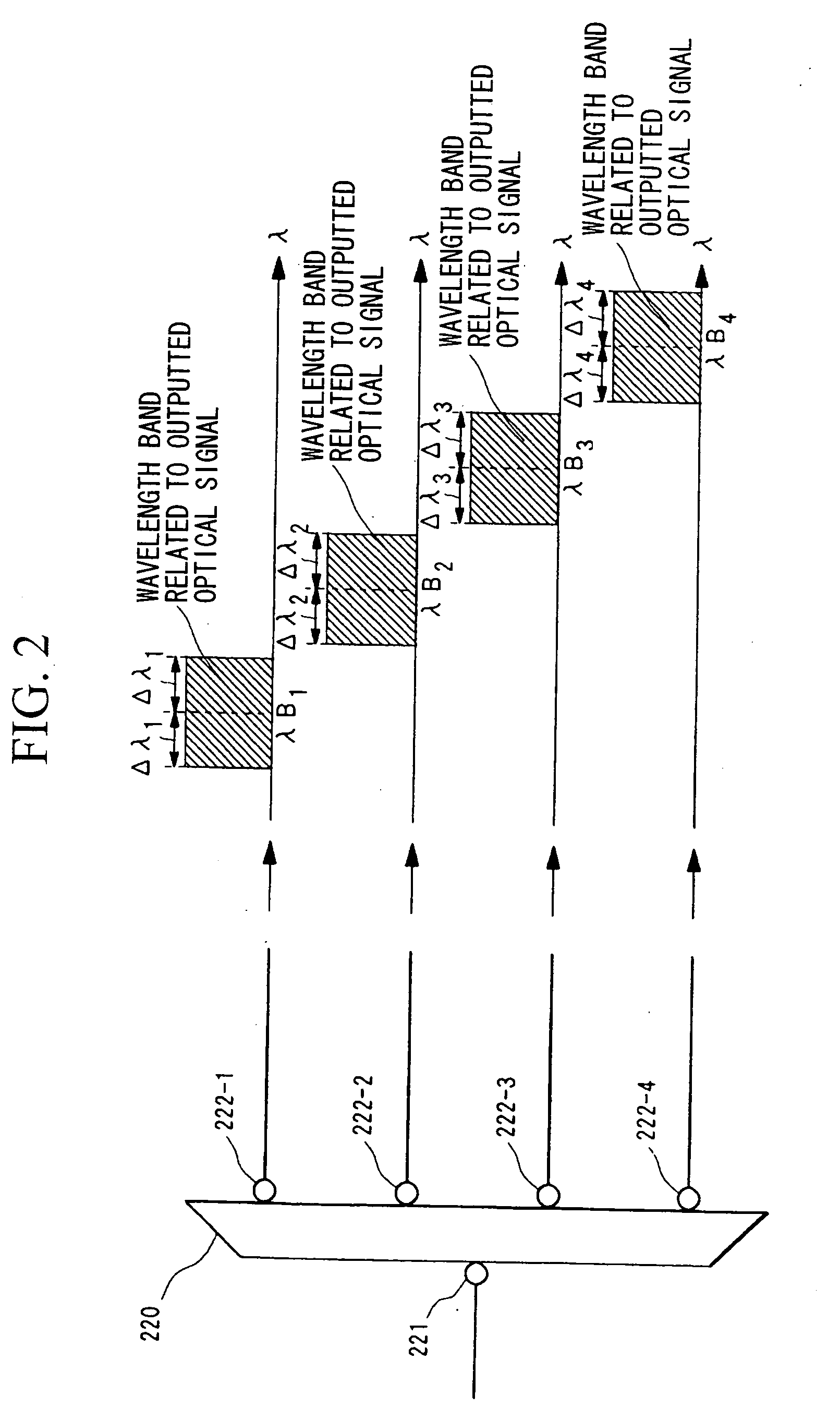
[0149] As has already been explained with regard to the first embodiment, although it is possible to establish four optical paths using four wavelength bands (the wavelength band λB1±Δλ1, the wavelength band λB2±Δλ2, the wavelength band λB3±Δλ3, and the wavelength band λB4±Δλ4), in the initial construction of an optical communication network system, as shown in FIG. 9, it is possible to provide an optical transmission section and an optical reception section of the single wavelength band λBp±Δλp (where p is an integer variable, and p is any one of 1, 2, 3, and 4) to each of the communication nodes 200-1 through 200-4, and thus to increase the wavelength bands according to the transmission capacity between the communication nodes (in FIG. 9, by way of example, the case of p=1 is shown).

[0150] For example, FIG. 10 is an example in which another optical transmission section 29...

third embodiment

The Third Embodiment

[0153] Next, the third embodiment according to the present invention will be explained with reference to FIG. 12. It should be understood that, in FIG. 12, to structural elements which are the same as in the first embodiment described above, the same reference symbols are affixed, and their explanation will be curtailed. In this embodiment, for each of the communication nodes 200-1 through 200-4, wavelength-tunable optical light source integrated optical transmitters 400-1 and 400-2 are implemented in the optical transmission section 290-2 and the optical transmission section 290-3, respectively, and moreover optical receivers 500-1 and 500-2 are implemented in the optical reception section 300-2 and the optical reception section 300-3,; respectively.

[0154] The output port of the wavelength-tunable optical light source integrated optical transmitter 400-1 is connected to the input port 230-12 of the wavelength-band multiplexer 230, while the output port of the w...


PUM


Abstract

An optical communication network system and a wavelength-routing device and a communication node therefor are provided which can easily increase the optical paths between communication nodes, which are capable of expanding transmission capacity, and which excel in flexibility and expandability. An optical signal within a wavelength band (λBm±Δλm) which has been transmitted from a predetermined communication node (200-1 through 200-4) is subjected to wavelength-band demultiplexing of the wavelength bands by wavelength-band demultiplexers (220-1 through 220-4) of a wavelength-routing device (210), and is then subjected to wavelength-routing by arrayed-waveguide gratings (241 through 244) according to the wavelength bands, and furthermore is multiplexed with optical signals of other wavelength bands by wavelength-band multiplexers (230-1 through 230-4), and after having been outputted, is transmitted to a communication node. In this manner, by varying the wavelength band (λBm±Δλm) of the wavelength of the optical signal which is transmitted from the communication node, it becomes possible to establish a single optical path between the communication nodes for each wavelength band.

Description

TECHNICAL FIELD [0001] The present invention relates to an optical communication network system which takes advantage of wavelength-routing and which establishes communication between a plurality of communication nodes by route control according to the wavelength of an optical signal, to a wavelength-routing device thereof, and to a communication node. [0002] Furthermore, the present invention relates to an optical path management method and a device therefor which are useful when applied to such an optical communication network system, and to a technique for managing the optical path in an optical cross connect device which forms an optical network using an optical wavelength division multiplexing technique, and in particular an optical cross connect device which consists of a combination of a plurality of small scale optical matrix switches, and which establishes an optical path between any desired communication nodes among a maximum of N (where N is an integer greater than or equ...

Claims


Application Information

Patent Timeline
IPC IPC(8): H04J14/02H04J14/00H04B10/27H04B10/291H04L12/931H04Q11/00
CPCH04J14/0209H04J14/021H04J14/0212H04Q2011/0075H04J14/0217H04Q11/0005H04J14/0213
Inventor MORIWAKI, OSAMUOKADA, AKIRANOGUCHI, KAZUTOTANOBE, HIROMASAMATSUOKA, MORITOSAKAMOTO, TAKASHI
Owner NIPPON TELEGRAPH & TELEPHONE CORP
Learn More