Healing transmyocardial implant

a transmyocardial implant and implant technology, applied in the field of implants, can solve the problems of not facilitating full healing and achieve the effect of promoting healing

Inactive Publication Date: 2006-03-09
WILK PATENT DEVMENT +1
View PDF4 Cites 28 Cited by
  • Summary
  • Abstract
  • Description
  • Claims
  • Application Information

AI Technical Summary

Benefits of technology

[0009] According to a preferred embodiment of the present invention, a transmyocardial implant is disclosed for establishing a blood flow path through a myocardium between a heart chamber and a lumen of a coronary vessel residing on an exterior of the heart. The implant includes a coronary portion sized to be received with the vessel. A myocardial portion is sized to pass through the myocardium into the heart chamber. A transition portion connects the coronary and myocardial portions for directing blood flow from the myocardial portion and into the coronary portion. The coronary portion and the myocardial portion have an open construction for permitting tissue growth across a wall thickness of the coronary portion and the myocardial portion. The myocardial portion includes an agent for controlling the coagulation cascade and platelet activation, and promoting healing.

Problems solved by technology

While such materials are proven in use in a wide variety of products (e.g., heart valve components), they do not facilitate full healing.

Method used


Image

  • Healing transmyocardial implant
  • Healing transmyocardial implant
  • Healing transmyocardial implant

Examples


Embodiment Construction

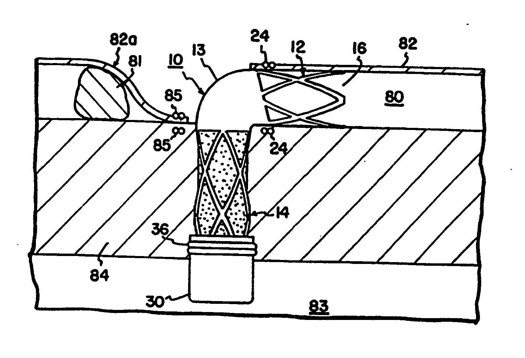
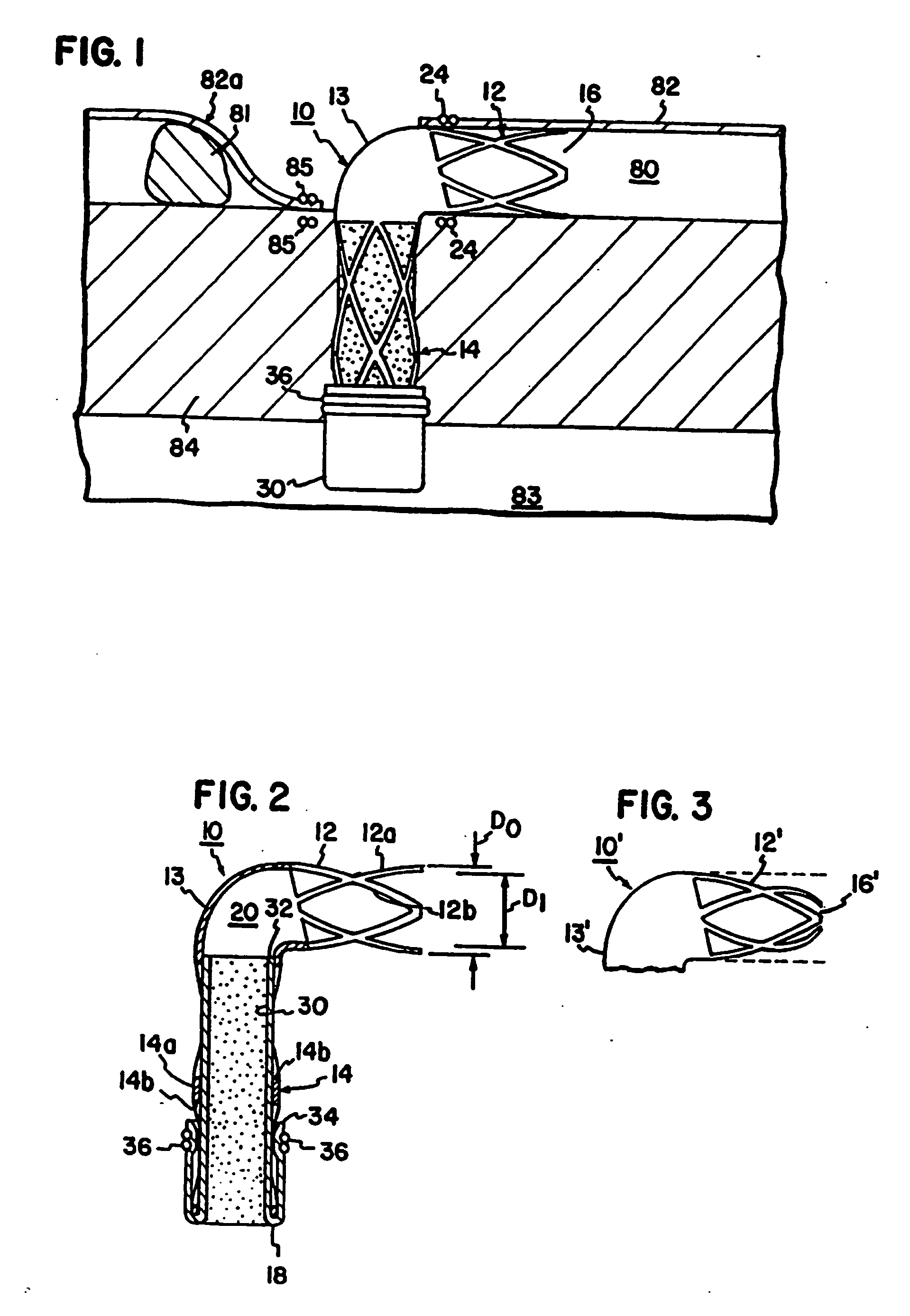
[0016] With initial reference to FIG. 1, a conduit 10 is shown in the form of an L-shaped tube. The conduit 10 may be formed of titanium or other biocompatible material. The material of the conduit 10 is preferably radially rigid material in order to withstand contraction forces of the myocardium. By way of non-limiting example, the tube will have an outside diameter D0 of about 3 millimeters and an internal diameter D1 of about 2.5 millimeters to provide a wall thickness of about 0.25 millimeters.

[0017] The tube 10 has a coronary portion 12 sized to be received within the lumen of a coronary vessel such as the lumen 80 of a coronary artery 82 distal to an obstruction 81 as illustrated in FIG. 1. The conduit 10 has a myocardial portion 14 extending at a right angle to the axis of portion 12. The myocardial portion 14 is sized to extend from the coronary artery 82 directly through the myocardium 84 and protrude into the left ventricle 83 of a patient's heart.

[0018] The coronary por...


PUM

PropertyMeasurementUnit
thicknessaaaaaaaaaa
internal diameter D1aaaaaaaaaa

Abstract

A transmyocardial implant establishes a blood flow path through a myocardium between a heart chamber and a lumen of a coronary vessel residing on an exterior of the heart. The implant includes a coronary portion sized to be received within the vessel. A myocardial portion is sized to pass through the myocardium into the heart chamber. A transition portion connects the coronary and myocardial portions for directing blood flow from the myocardial portion to the coronary portion. The coronary portion and the myocardial portion have an open construction for permitting tissue growth across a wall thickness of the coronary portion and the myocardial portion. The myocardial portion includes an agent for controlling a coagulation cascade and platelet formation.

Description

BACKGROUND OF THE INVENTION [0001] 1. Field of the Invention [0002] This invention pertains to an implant for passing blood flow directly between a chamber of the heart and a coronary vessel. More particularly, this invention pertains to such an implant with an enhance design for promoting a healed layer of cells on an interior of the implant. [0003] 2. Description of the Prior Art [0004] Commonly assigned U.S. Pat. No. 5,755,682 issued May 26, 1998 and commonly assigned and co-pending U.S. patent application Ser. No. 08 / 882,397 filed Jun. 25, 1997, entitled “Method and Apparatus for Performing Coronary Bypass Surgery”, and filed in the name of inventors Mark B. Knudson and William L. Giese (published as PCT International Application Publication No. WO 98 / 06356) both teach an implant for defining a blood flow conduit directly from a chamber of the heart to a lumen of a coronary vessel. In one embodiment, an L-shaped implant is received within a lumen of a coronary artery and passed ...

Claims


Application Information

Patent Timeline
Patent Type & Authority Applications(United States)
IPC IPC(8): A61M5/00A61B17/00A61L27/00A61B17/04A61B17/11A61F2/00A61F2/02A61F2/06A61F2/82A61F2/94A61L33/10
CPCA61B17/04A61F2230/0054A61B2017/00252A61F2/06A61F2/064A61F2/07A61F2/2493A61F2/91A61F2/915A61F2/94A61F2/958A61F2002/828A61F2002/91533A61F2002/9155A61F2002/91558A61F2250/0067A61F2220/0008A61B17/11
Inventor TWEDEN, KATHERINE S.VANNEY, GUY P.
Owner WILK PATENT DEVMENT
Why Eureka
Try Eureka