
Power device equipped with combustion engine and stirling engine

a technology of power devices and stirling engines, which is applied in the direction of machines/engines, reciprocating combination engines, greenhouse gas reduction, etc., can solve the problems of low brake horsepower of stirling engines, and achieve the effect of reducing the fuel consumption of combustion engines

Inactive Publication Date: 2006-03-16
HONDA MOTOR CO LTD
View PDF4 Cites 17 Cited by
  • Summary
  • Abstract
  • Description
  • Claims
  • Application Information

AI Technical Summary

Benefits of technology

[0011] The present invention has the following effects. The generator driven by the maximum or substantially maximum brake horsepower generates the maximum or substantially maximum power. Thus, the largest possible part of the thermal energy of the waste heat can be recovered, the frequency of driving the auxiliary machinery by the electric motor driven by sufficient power increases and thereby the fuel consumption of the combustion engine can be further reduced.
[0013] Thus, when the power generated by the generator is insufficient for driving all the predetermined number of auxiliary machines by the electric motor, the number of the auxiliary machines to be driven by the electric motor is changed according to the power generated by the generator and thereby the fuel consumption of the combustion engine is reduced accordingly. The combustion engine drives the auxiliary machines when the generator is unable to generate sufficient power due to the insufficient thermal energy of the waste heat and the resultant low brake horsepower of the Stirling engine.
[0014] Consequently, the following effects are obtained. Since the electric motor drives as many ones as possible of the plurality of auxiliary machines according to the power generated by the generator, the fuel consumption of the combustion engine can be reduced. Even if the generator and the battery are unable to supply sufficient power, the auxiliary machines can be surely driven by the combustion engine.

Problems solved by technology

When the waste heat generated by the combustion engine has insufficient thermal energy, the brake horsepower of the Stirling engine is low, and the generator is unable to generate power sufficient for driving the auxiliary machinery, the auxiliary machinery can be driven in a mode capable of sufficiently exercising its functions by power supplied from the battery charged by power generated by the generator.

Method used


Image

  • Power device equipped with combustion engine and stirling engine
  • Power device equipped with combustion engine and stirling engine
  • Power device equipped with combustion engine and stirling engine

Examples


Embodiment Construction

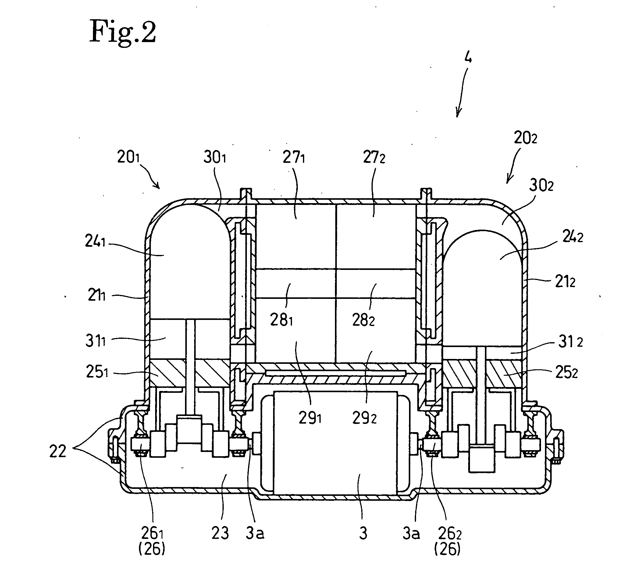
[0023] A preferred embodiment of the present invention will be described with reference to FIGS. 1 to 4.

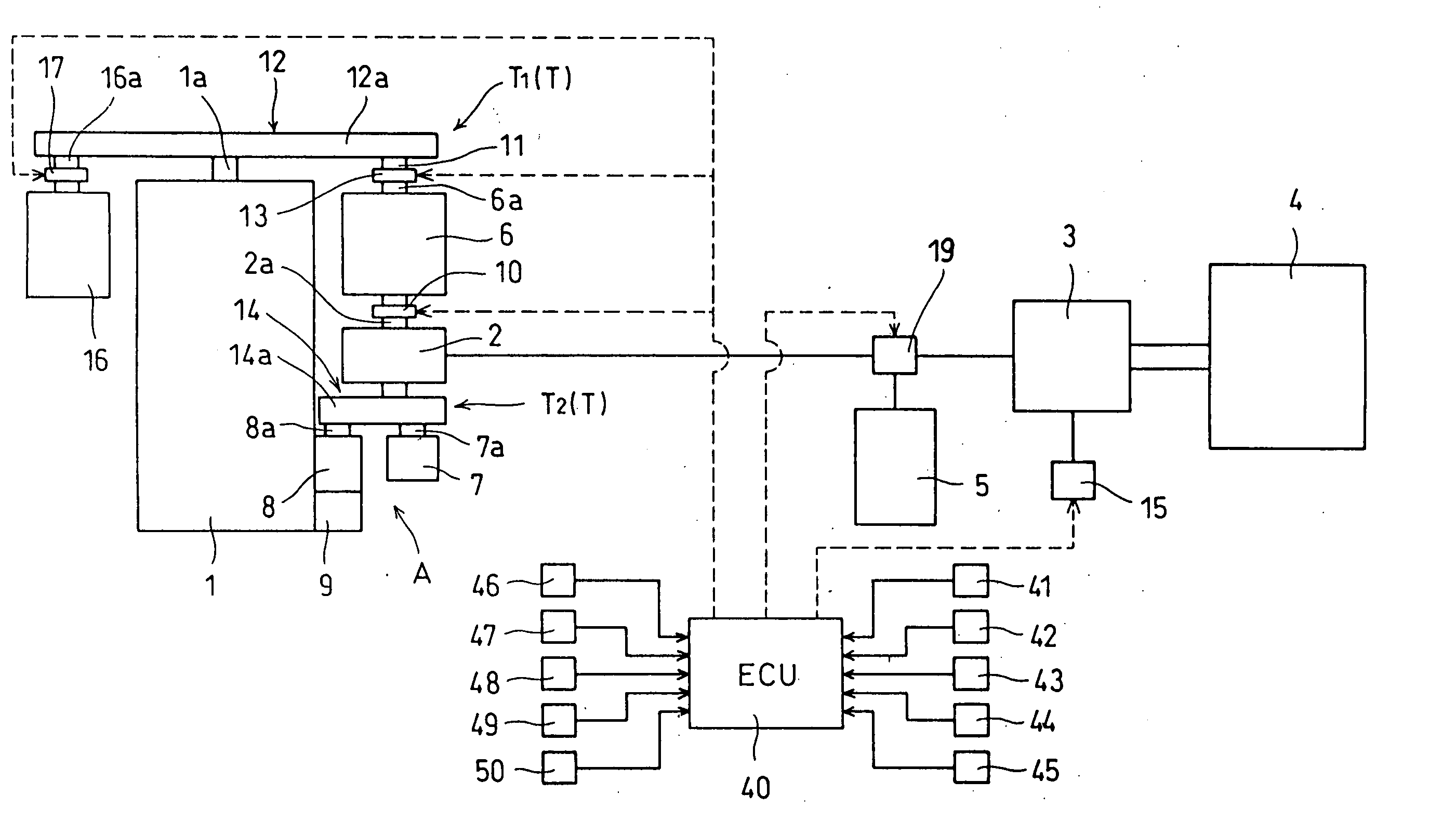
[0024] Referring to FIG. 1, a power unit in a preferred embodiment of the present invention includes a water-cooled multicylinder internal combustion engine 1, a predetermined number of auxiliary machines, an electric motor 2, a generator 3, a Stirling engine 4 for driving the generator 3, a battery 5, and a control system including a control unit (hereinafter, referred to as “ECU”) 40. The power unit is mounted on a vehicle, and the internal combustion engine 1 serves as a prime mover for driving the vehicle.

[0025] The internal combustion engine 1 has pistons fitted in cylinders for reciprocating motion, and a crankshaft la driven for rotation by the pistons. The pistons are driven by the pressure of a combustion gas produce by the combustion of an air-fuel mixture produced by fuel ejected into the cylinders by fuel injection valves and air supplied into the cylinders through a...


PUM


Abstract

A power unit for a vehicle, such as an automobile, includes an internal combustion engine 1 as a prime mover for the vehicle, a generator 3, and a Stirling engine 4 for driving the generator 3. The Stirling engine 4 uses the exhaust gas discharged by the internal combustion engine 1 as a high-temperature heat source. Power generated by the generator 3 is supplied to an electric motor 2 for driving auxiliary machines 7, 8 and 9, and to a battery 5 for supplying power to the electric motor 2. The engine speed of the Stirling engine 4 is controlled through the control of the load on the generator 3 by a field regulator 15. An optimum engine speed of the Stirling engine 4 is determined such that the brake horsepower of the Stirling engine 4 increases to a maximum or substantially maximum brake horsepower. The fuel consumption of the internal combustion engine 1 as the prime mover that produces waste heat as a high-temperature heat source for the Stirling engine 4 is reduced, and the auxiliary machines are driven so as to fully exercise their functions even in a state where the brake horsepower of the Stirling engine 4 is low.

Description

TECHNICAL FIELD [0001] The present invention relates to a power unit including a combustion engine as a power source, a Stirling engine using waste heat from the combustion engine as a heat source, and auxiliary machines. More specifically, the present invention relates to a power unit including a combustion engine, a Stirling engine and auxiliary machines, and capable of using power generated by a generator driven by the Stirling engine for driving the auxiliary machines. BACKGROUND ART [0002] Stirling engines for driving a generator are disclosed in JP 64-75865 A and JP 2002-266701 A. The Stirling engine disclosed in JP 64-75865 A drives a refrigerant compressor included in a heat pump, and a generator. When the engine speed of the Stirling engine changes due to changes in air-conditioning load and the atmospheric condition, a field regulator included in the generator regulates the magnetic field of the generator to control the engine speed of the Stirling engine. Consequently, a ...

Claims


Application Information

Patent Timeline
IPC IPC(8): F02G1/04F01B29/10F01N5/02F02G1/043F02G1/06F02G5/02
CPCB60K8/00F02B67/00F02B73/00Y02T10/166F02G1/06F02G5/02F02G2254/15F02G1/043Y02E20/30Y02T10/12F01K23/10F02B67/08
Inventor MORI, MASAYOSHI
Owner HONDA MOTOR CO LTD
Learn More