Marine vessel corrosion control system

a corrosion control system and marine vessel technology, applied in the direction of hulls, vessel cleaning, vessel construction, etc., can solve the problems of deterioration of underwater metallic parts, endangerment of the watertight integrity of the boat hull, and easy corrosion of marine vessel metal parts submerged underwater

Inactive Publication Date: 2006-03-16
SICA JOSEPH D +1
View PDF14 Cites 18 Cited by
  • Summary
  • Abstract
  • Description
  • Claims
  • Application Information

AI Technical Summary

Benefits of technology

[0007] The present invention relates to a marine vessel corrosion control system. The present invention includes the following interrelated objects, aspects and features:

Problems solved by technology

In the prior art, it is well known that metallic parts of a marine vessel submerged underwater are susceptible to corrosion through the process known as electrolysis.
Galvanic corrosion is typically a slow process, however, over a lengthy period of time, it can result in deterioration of underwater metallic parts and in endangerment of the watertight integrity of a boat hull.
Those of ordinary skill in the art realize that galvanic corrosion promotes deterioration and failure of underwater parts made of alloys of bronze.
Left unprotected, such alloys waste away resulting in failure of component parts.
Under circumstances where stray currents arise from current leakage from a vessel as well as from external power sources, galvanic corrosion can be much more rapid and catastrophic.
Such systems can be effective but, if they fail, for any reason, the boat owner is left with a completely unprotected vessel in which the submerged metallic component parts are immediately subject to galvanic corrosion.
None of the other patents teaches breaking a connection of a sacrificial zinc anode using an energized magnetic coil or digital switch.

Method used


Image

  • Marine vessel corrosion control system
  • Marine vessel corrosion control system
  • Marine vessel corrosion control system

Examples


Embodiment Construction

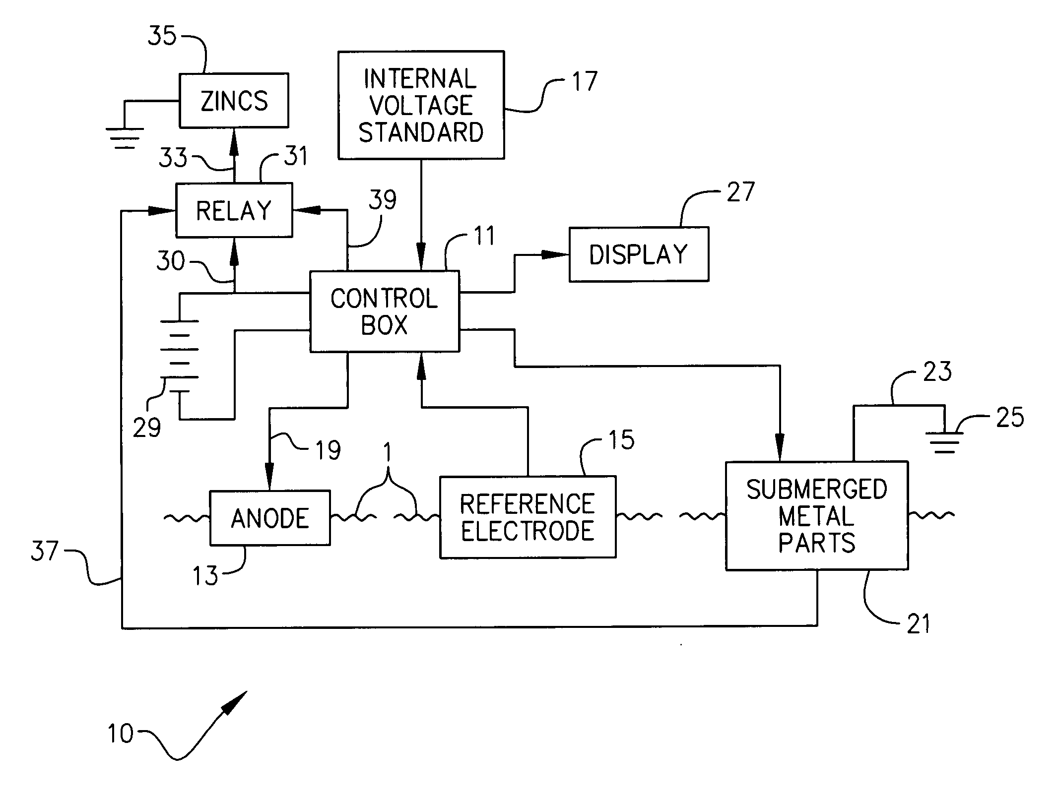
[0022] Reference is first made to FIG. 10 so that an overview of the components and operation of the present invention will be understood. In FIG. 10, the present invention is generally designated by the reference numeral 10 and is seen to include a control box 11 that controllably supplies electrical current to an anode 13 submerged within a body of water schematically designated by the reference numeral 1. A reference electrode 15 is also submerged within the body of water 1 and the control box 11 samples the water potential through the use of the electrode 15 which may, if desired, comprise a silver-silver chloride reference electrode. By closed loop feedback, the control box 11 compares the reference electrode voltage with an internal stabilized voltage standard shown as reference numeral 17 in FIG. 10. Responsive to comparing the voltage standard 17 with the reference electrode 15 voltage, the control box 11 supplies current through the anode 13 via the conductor 19, which conv...


PUM


Abstract

A marine vessel corrosion control system contemplates redundant protection for a marine vessel against the effects of galvanic corrosion. The vessel is equipped with typical zinc anodes interconnected together and attached to metallic components to be protected from galvanic corrosion. A reference electrode immersed in the water provides signals to a control box representative of electrode voltage as compared to an internal stabilized voltage standard. The control box compares the reference electrode voltage with the internal stabilized voltage standard and feeds current through a hull mounted anode into the water and through the submerged metal parts of the vessel. A relay allows selective interruption of the connection between the passive zincs and the vessel ground and selective closing of that circuit. The relay is connected to the control box and when the control box fails in any way, this failure is sensed and results in deactivation of the normally closed relay to electrically interconnect the passive zincs to the vessel ground until the active galvanic corrosion control system is repaired.

Description

BACKGROUND OF THE INVENTION [0001] The present invention relates to a marine vessel corrosion control system. In the prior art, it is well known that metallic parts of a marine vessel submerged underwater are susceptible to corrosion through the process known as electrolysis. Galvanic corrosion is typically a slow process, however, over a lengthy period of time, it can result in deterioration of underwater metallic parts and in endangerment of the watertight integrity of a boat hull. Those of ordinary skill in the art realize that galvanic corrosion promotes deterioration and failure of underwater parts made of alloys of bronze. Left unprotected, such alloys waste away resulting in failure of component parts. [0002] Under circumstances where stray currents arise from current leakage from a vessel as well as from external power sources, galvanic corrosion can be much more rapid and catastrophic. [0003] For many years, boat manufacturers have included in the boats they manufacture num...

Claims


Application Information

Patent Timeline
Patent Type & Authority Applications(United States)
IPC IPC(8): B63B59/00
CPCC23F13/04B63B59/00C23F13/22C23F2213/21C23F2213/31
Inventor SICA, JOSEPH D.JACKSON, MAURICE L.
Owner SICA JOSEPH D
Why Eureka
Try Eureka