Oil circulation retention system and method

a technology of oil circulation and storage system, applied in the direction of crankshafts, engine lubrication, shafts, etc., can solve the problems of increased design tank size, lubricant may be changed from time to time, and generally prolonging the useful life of bearing lubrication

Active Publication Date: 2006-03-16
DODGE ACQUISITION CO +1
View PDF7 Cites 34 Cited by
  • Summary
  • Abstract
  • Description
  • Claims
  • Application Information

AI Technical Summary

Benefits of technology

[0010] The present invention provides a novel technique for a bearing oil circulation system to respond to such needs. The technique utilizes check valves in the oil circuit to prevent draining of oil to the oil tank and thus prevents overflow of the tank. A check valve situated in the oil supply piping (pump outlet to the bearing) requires a certain threshold inlet pressure to open. This threshold pressure on the supply piping also opens a pilot-operated check valve situated in the return piping. The return check valve generally requires the same or less pressure to open than that needed to open the supply check valve. As the pump is shut down and the pump outlet pressure decays, the pump outlet (supply) check valve and the return pilot-operated check valve both automatically close, preventing oil in the supply and return lines from draining to the oil system tank. Thus, the problem of oil tank overflow is mitigated without the expensive and cumbersome option of installing a larger oil tank. In addition, the oil level may be maintained in the bearing housing to provide static lubrication so that the bearing may continue to operate.
[0013] In yet another embodiment, a method for supplying lubricant to a bearing includes pressurizing a supply line with oil, opening a supply check valve and a return pilot-operated check valve, and circulating oil through a bearing or gear reducer. Further, the supply line may be depressured, and the supply check valve and a return pilot-operated check valve automatically close to prevent draining of oil to the oil source.

Problems solved by technology

Moreover, lubrication of the bearings generally prolongs the useful life by reducing corrosion and wear, and by providing for sealing and cooling of the bearing.
Moreover, lubricants may be changed from time to time because their properties may deteriorate as a result of aging and contamination of the lubricants.
However, for long runs of supply and return piping, the designed tank size may increase to the point where the layout or handling of the tank becomes cumbersome (e.g., difficult to install on a small skid unit), or where the cost of the tank becomes prohibitive.
Furthermore, design of a tank capacity based on the piping volume is not applicable where the piping layout is not known prior to the design and fabrication of the oil tank.
For tanks with a relatively small volume or a high normal operating level (small vapor space), the oil that drains from the piping may overfill the tank, especially with long runs of supply and return piping.
As the tank overfills, the oil may leak from the tank (e.g., through the tank breather) and may create an oil flood on the surrounding ground or floor, as well as cause loss of oil in the total system.
Such loss can lead to emptying of the tank and bearing sump, which can then adversely affect the operation of the pump and the bearings.
As indicated, increasing the size of the oil tank significantly such that any oil flowing back will not cause over filling of the tank requires prior knowledge of the size and length of the connecting pipes, which is often not available.
Moreover, even where the piping data is available, the size of the tank may become cumbersome or cost prohibitive, and requires multiple product offerings.

Method used


Image

  • Oil circulation retention system and method
  • Oil circulation retention system and method
  • Oil circulation retention system and method

Examples


Embodiment Construction

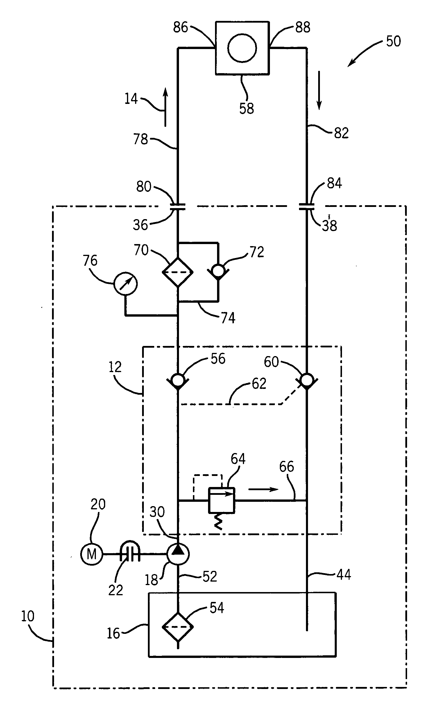
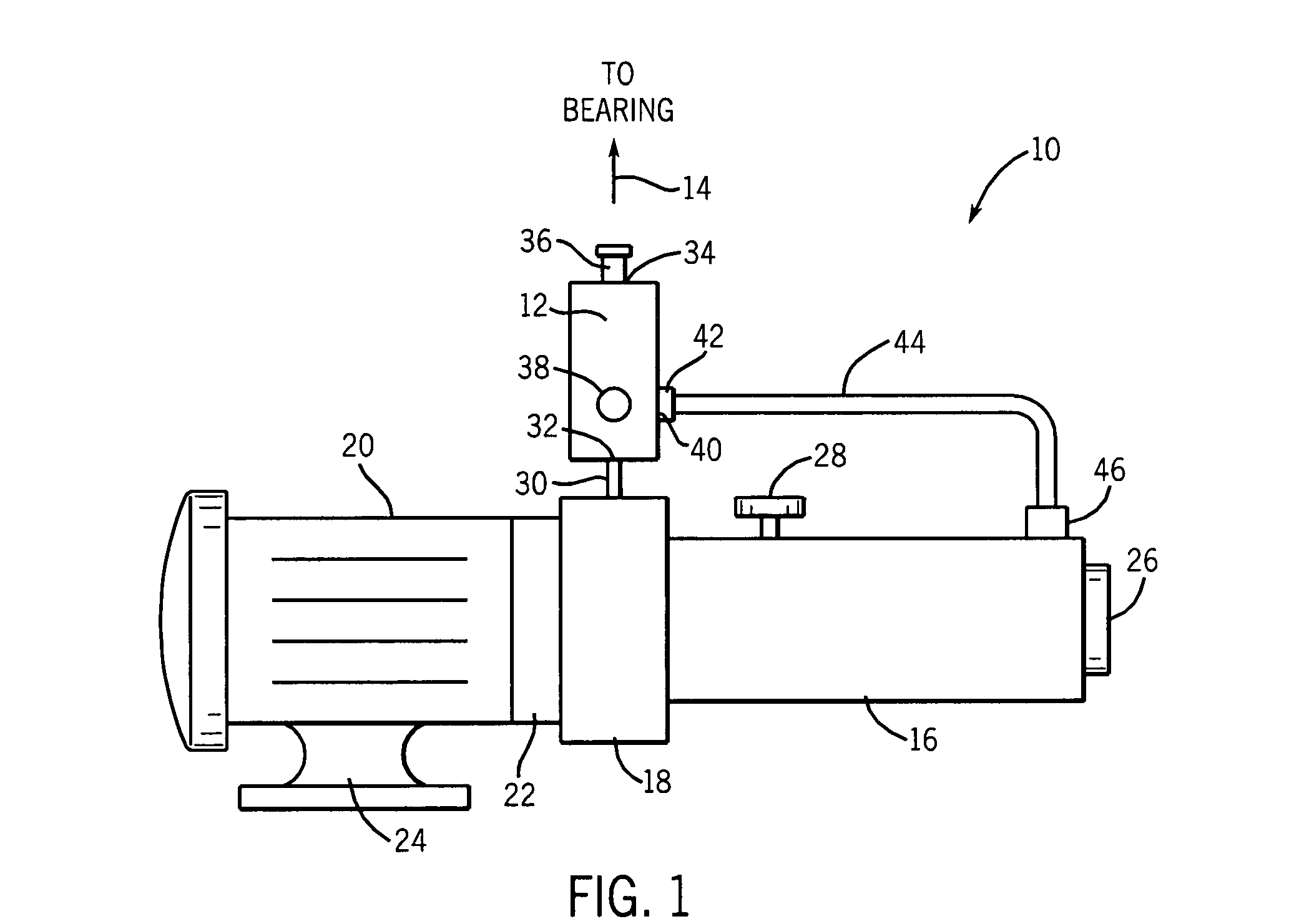
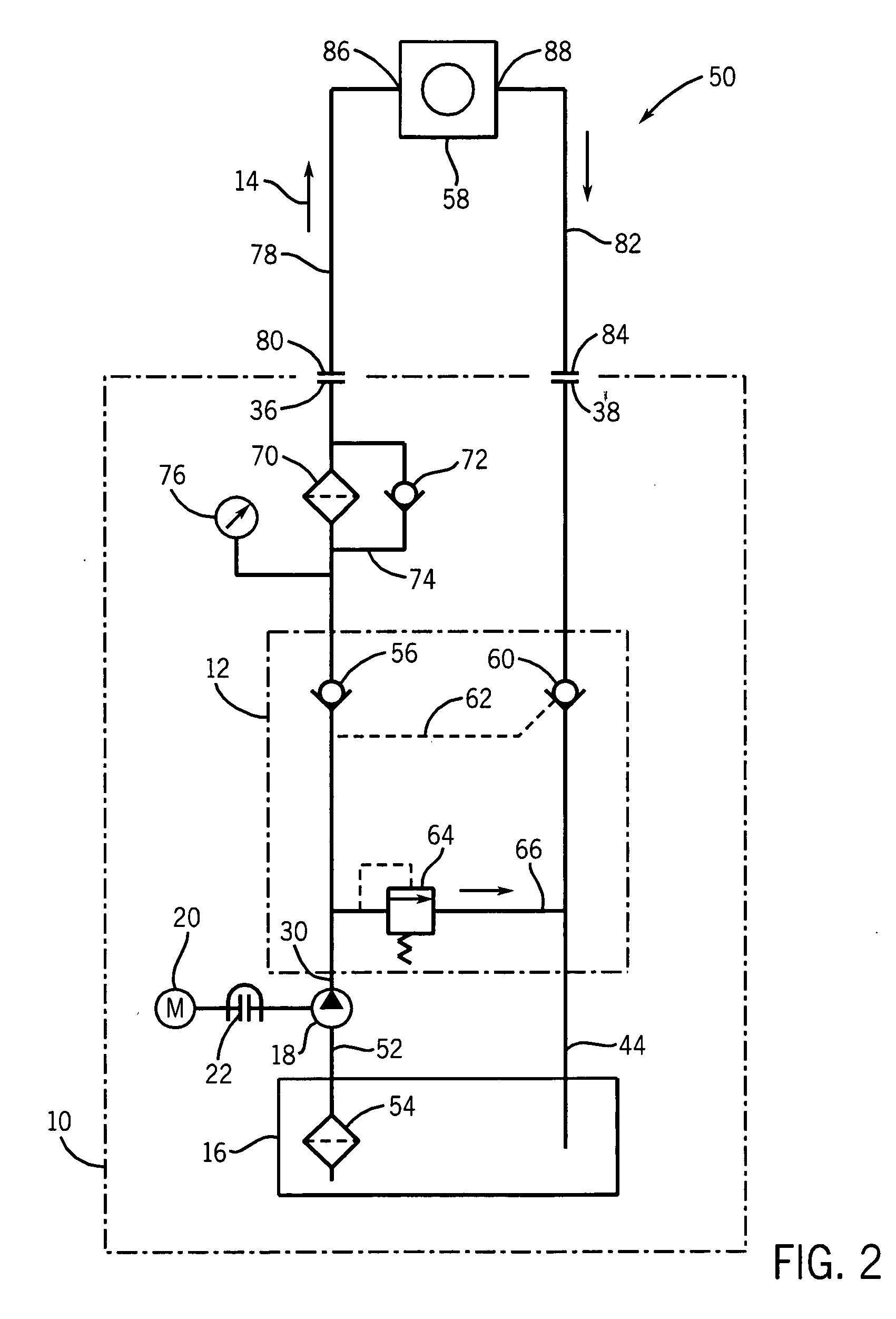
[0019] Turning now to the drawings and referring to FIG. 1, a bearing lubrication unit 10 is shown. In this illustrated embodiment, the bearing lubrication unit 10 is a pumped oil circulation unit, and includes an anti-flooding or oil-retention block 12, which may comprise a manifold for mounting cartridge valves including check valves. In particular, as discussed below, the oil-retention block 12 may comprise a supply check valve, a return check valve, and a relief valve. In general, the bearing lubrication unit 10 provides an oil supply 14 from an oil tank 16 via pump 18 and through a supply conduit to one or more bearings or gear reducers or other mechanical components. In this example, an oil pump motor 20 is close-coupled to the oil pump 18 via a C-face adapter 22. A motor support 24 is positioned under motor 20 to support the motor 20 and pump 18 assembly.

[0020] A level element or indicator, such as a sight glass 26, measures the level of lubrication oil (e.g., a light minera...


PUM


Abstract

A bearing lubrication (oil circulation) system having a check valve configuration for preventing overflow of an oil reservoir or tank. The pressurized oil circulation system may comprise a pump that pressurizes oil from the tank and circulates the oil through a supply conduit to a bearing, and returns the oil to the tank through a return conduit. The system may include a check valve disposed in the supply conduit and a pilot-operated check valve disposed in the return conduit. The pilot may be taken from the supply conduit upstream of the check valve disposed on the supply conduit. When pressure is discharged from the oil circulation, such as with shutdown of a circulation pump, the check valves automatically close and thus prevent oil contained in the supply and return conduits from draining (i.e., by gravity) to the oil tank. Therefore, flooding of the oil tank with excessive oil is prevented. Furthermore, loss of oil from the bearing sump is also prevented.

Description

BACKGROUND OF THE INVENTION [0001] The present invention relates generally to the field of bearings and the lubrication of such bearings. More particularly, the invention relates to a novel arrangement for retaining lubricant in a bearing lubrication system upon shutdown of the system. [0002] Wide varieties of bearings and other power transmission components are available and are currently in use throughout a range of industrial applications. Bearings are generally used for facilitation of rotational movement in a mechanical application, and typically include a plurality of bearing elements situated in a housing. Depending upon the application and the anticipated loading, the bearing elements may be journal bearings, needle bearings, roller bearings, ball bearings, and so forth. Moreover, lubrication of the bearings generally prolongs the useful life by reducing corrosion and wear, and by providing for sealing and cooling of the bearing. [0003] Lubrication may reduce friction betwee...

Claims


Application Information

Patent Timeline
Patent Type & Authority Applications(United States)
IPC IPC(8): F16N29/00
CPCF16C33/1085F16N2210/14F16N7/40
Inventor EL-IBIARY, YEHIA
Owner DODGE ACQUISITION CO
Why Eureka
Try Eureka