Suspension apparatus for vehicle

a suspension apparatus and vehicle technology, applied in mechanical apparatus, braking systems, transportation and packaging, etc., can solve the problems of creaking sound, poor flatness of mounting surfaces, local wear of pads, etc., and achieve the effect of high flatness

Inactive Publication Date: 2006-03-16
TOYOTA JIDOSHA KK
View PDF10 Cites 19 Cited by
  • Summary
  • Abstract
  • Description
  • Claims
  • Application Information

AI Technical Summary

Benefits of technology

[0009] No bent edge is formed at the open end of the knuckle. Therefore, the outer side surface and inner side surface of the open end are less likely to be influenced by distortions stemming from bending and welding, and can have a high degree of flatness. The open end of the knuckle does not project outward by bent edges, so that a space corresponding to the reduction in projection can be used as a part of installation space for the brake mechanism.

Problems solved by technology

However, if such a brake mechanism is attached to the knuckle of the above-described conventional suspension apparatus, various problems arise.
Therefore, a mounting surface of the knuckle to which a brake mechanism is mounted is influenced by distortions stemming from bending and welding, so that the mounting surface has poor flatness.
In the case where a brake mechanism is attached to the mounting surface of the knuckle having poor flatness, pads of the brake mechanism are not disposed in parallel to a disc rotor, so that the pads come into nonuniform contact with the disc rotor with resultant local wear of the pads, and creaking sound is generated during braking.
However, securing a sufficient installation space is difficult.

Method used


Image

  • Suspension apparatus for vehicle
  • Suspension apparatus for vehicle
  • Suspension apparatus for vehicle

Examples


Embodiment Construction

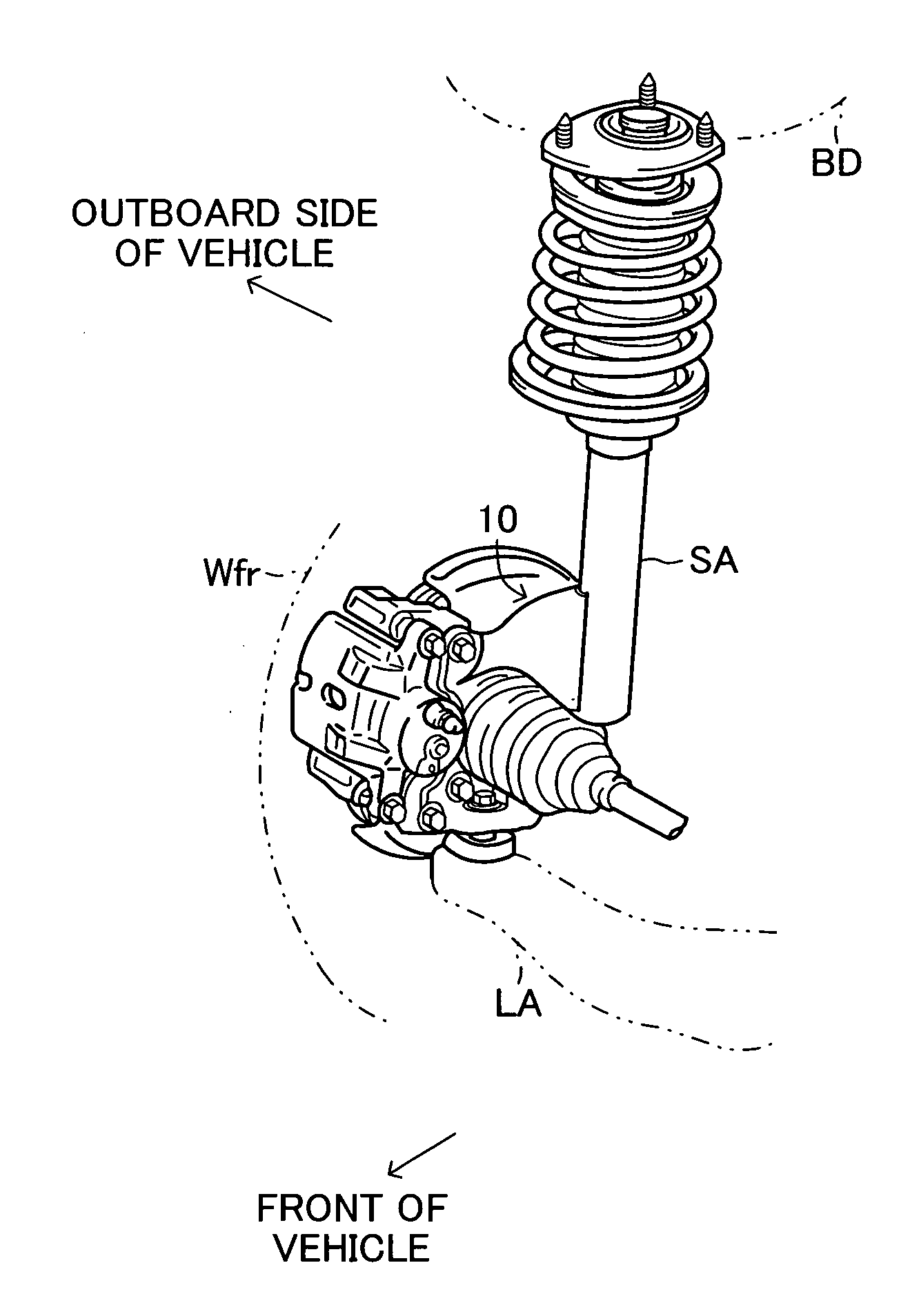
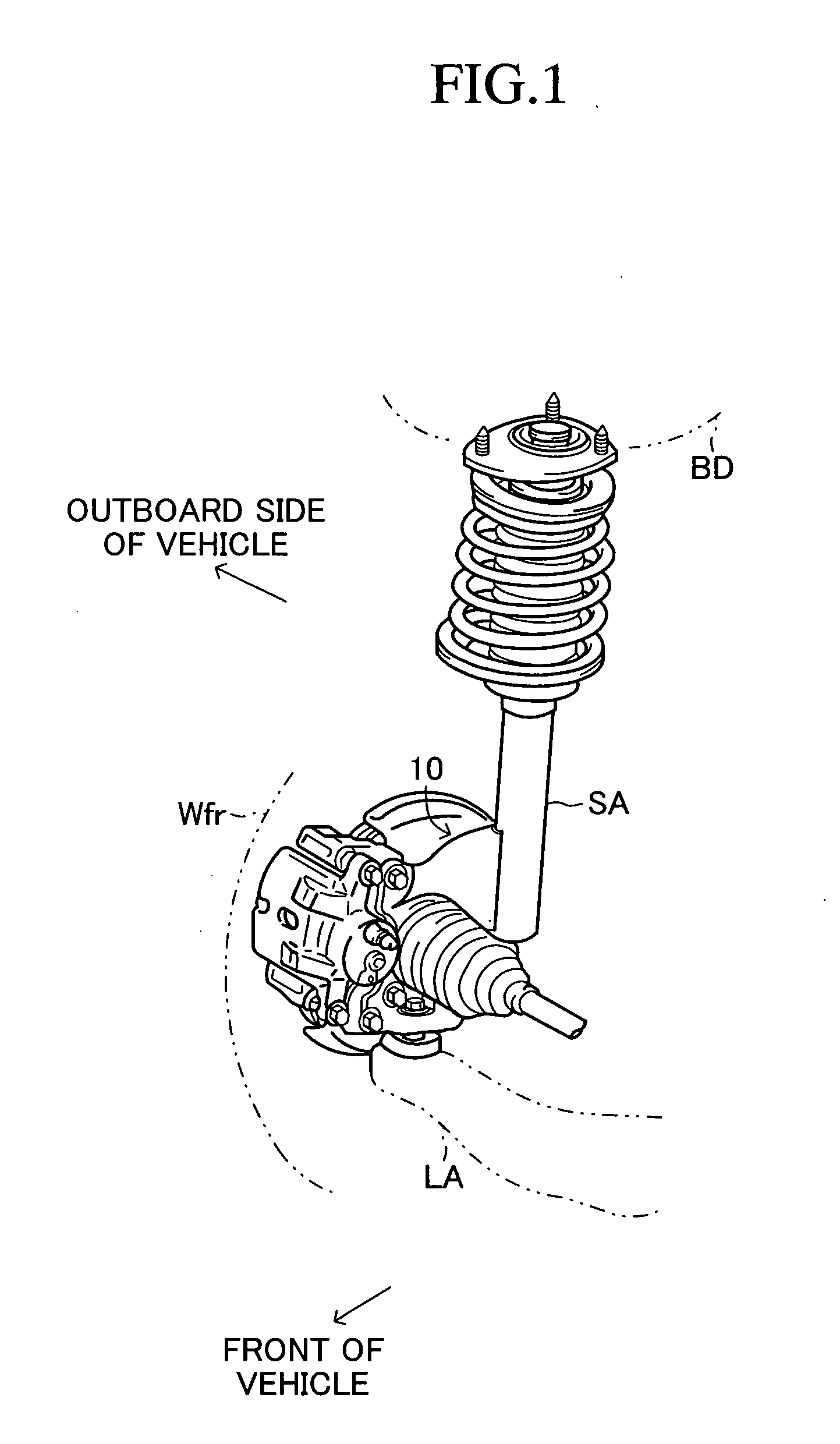
[0022] An embodiment of the present invention will now be described with reference to the drawings. FIG. 1 is an overall schematic view of a strut-type suspension apparatus which is a suspension apparatus for a vehicle according to the embodiment. FIG. 1 shows only a suspension apparatus for a front right wheel Wfr, which is a driven wheel, as a representative. The suspension apparatus includes a knuckle 10. The knuckle 10 is interposed between a shock absorber SA, which supports a vehicle body BD, and a lower arm LA, which is a wheel-side support member. The knuckle 10 supports the front right wheel Wfr such that the front right wheel Wfr can be steered and rotated.

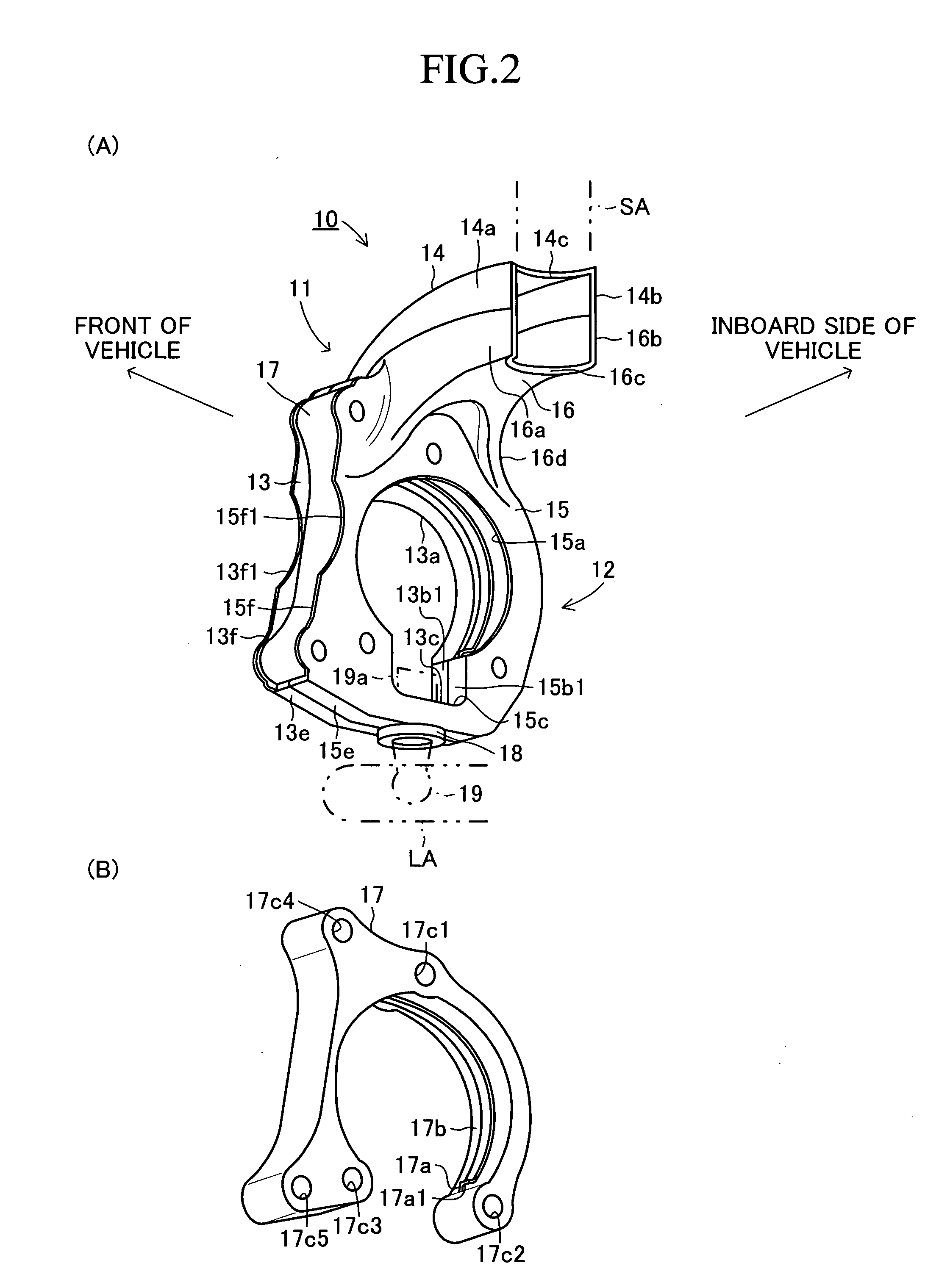
[0023] As shown in FIGS. 2A and 3, the knuckle 10 includes two plate members 11 and 12 each press-formed into a generally L-like shape as viewed from the front of the vehicle. Predetermined corresponding portions of the circumferential edges of the plate members 11 and 12 are bent such that the corresponding portions ab...


PUM


Abstract

A knuckle of a suspension apparatus includes first and second press-formed plate members, and a spacer disposed therebetween. The first and second plate members are welded together in a state in which rear end bent edges and lower end bent edges of respective lower walls of the first and second plate members abut each other, and front end bent edges and rear end bent edges of respective upper walls of the first and second plate members abut each other. Open ends having no bent edge are formed at the front ends of the lower walls. A disc brake is attached to the outer side surface of the lower wall of the first plate member to be located outside the open end of the first plate member, or is attached to the inner side surfaces of the lower walls of the first and second plate members to be located between the open ends of the first and second plate members.

Description

BACKGROUND OF THE INVENTION [0001] 1. Field of the Invention [0002] The present invention relates to a suspension apparatus for a vehicle which includes a knuckle for supporting a wheel. [0003] 2. Description of the Related Art [0004] As disclosed in, for example, Japanese Patent Application Laid-Open (kokai) No. H10-129225, there has conventionally been known a suspension apparatus for a vehicle in which a knuckle is constituted by two press-formed plate members. In the suspension apparatus, the plate members that constitute the knuckle are bent, by means of press forming, along the nearly entire portinos of their circumferences. As a result of bending, bent edges are formed on the two plate members such that the bent edges can overlap each other. The two plate members are fixed together by means of welding performed along the bent edges. [0005] In general, a brake mechanism for braking a wheel is attached to the knuckle of such a suspension apparatus. However, if such a brake mech...

Claims


Application Information

Patent Timeline
Patent Type & Authority Applications(United States)
IPC IPC(8): B60T1/06
CPCB60G2206/8201F16D55/22F16D55/226F16D2055/0008F16D2055/0012B60G2206/50B60G11/15B60G2200/142B60G2202/12B60G2202/312B60G2204/129B60G3/06
Inventor MURATA, SATOSHI
Owner TOYOTA JIDOSHA KK
Why Eureka
Try Eureka