Tamper evident container seal with integral pull opener

a technology of pull opener and container seal, which is applied in the direction of sealing, liquid handling, caps, etc., can solve the problems of weakness in the multi-layered seal only in the area of the c-shaped breaking pattern, and achieve the effect of easy opening, easy breaking and high resistan

Active Publication Date: 2006-03-16
JACKMAN BRIAN FRANCIS
View PDF71 Cites 18 Cited by
  • Summary
  • Abstract
  • Description
  • Claims
  • Application Information

AI Technical Summary

Benefits of technology

[0036] It is the object of the present invention to overcome the drawbacks and disadvantages of both, prior art, pull open, and non pull open, induction seals by providing a single type of pull open tamper evident seal that can serve in multiple capacities. My seal invention achieves this objective by creating the pull opener from the central portion of the broken open seal itself, which allows the seal to be easily opened without the rim contact portion of the seal having to be removed from the container rim.
[0037] The seal is fabricated from a first layer of leak proof frangible sheet material that is bonded by a second adhesive layer to a third layer of strengthening sheet material. A fourth layer of adhesive bonds the strengthening layer side of the seal to the container rim. The strengthening layer together with the two adhesive layers contain a duplicate C shaped cut out void area that forms a breaking pattern which turns the strengthening layer into a break and tear template layer. When the frangible layer is bonded to the template layer, the missing material in the cut out void area of the breaking pattern creates a weakness in the multi layered seal only in the area of the C shaped breaking pattern configuration. Bonding the differing layers together in this arrangement produces a leak proof multi layered seal that is weaker only where just the first frangible layer covers over the cut out void area of the breaking pattern configuration in both the template layer and the adhesive layers.
[0038] When a consumer applies a specific amount of external pressure by forcing a finger into the installed seal, the weakness created in the multi layered seal by the cut out void area forces the seal to break open and tear only in the configuration of the C shaped breaking pattern that follows in close proximity the inside perimeter of the rim, while the rim contact portion of the seal remains bonded to the container rim. The frangible layer does not delaminate from the template layer during the opening procedure. The broken open C shaped central portion of the seal then forms a pull tab that can be accessed and pinched between a consumers fingers.
[0039] One or more portions of the C shaped breaking pattern configuration are left uncut to form one or more connectors that attach the broken open central portion of the seal forming the pull tab, to the rim contact portion of the seal that remains bonded to the container rim. The one or more connectors prevent the pull tab from completely breaking away from the rim contact portion of the seal and then being pushed into the container when the seal is broken open. The one or more connectors also leave all or a portion of the pull tab in a downward vertical position in the open mouth of the container which allows a consumer to position a finger under the tab, and then pull it back out. After being pulled back out the tab can be pinched and pulled.
[0040] Constructing the seal in this manner allows the central portion of the installed seal to be easily broken open without an opening device to reveal the pull tab, while the contact portion of the seal remains bonded to the container rim. The ability of the central portion of the seal to be opened to create the pull tab, while the contact portion of the seal remains bonded to the rim, allows the seal to be bonded to the rim with adhesives that possess different bonding characteristics. The ability of the seal to be bonded to the container rim using adhesives with differing bonding characteristics in turn, allows the seal to serve in different capacities.
[0041] In a first embodiment the object of the invention is to provide a leak proof pull open tamper evident induction seal that is highly resistant to being removed from the container without being destroyed in the process, thereby preventing its reattachment. In this first embodiment the seal invention leaves behind the rim contact portion of the seal to provide telltale evidence when the seal is broken open and removed which allows the seal to serve in a tamper evident capacity on containers of ingestible products such as food, health care products, or pharmaceuticals etc., where product safety is of paramount importance.

Problems solved by technology

Bonding the template layer to the frangible layer strengthens the frangible layer everywhere except in the area of the breaking pattern by leaving only the first frangible layer covering over the C shaped cut out void configuration of the breaking pattern which in turn creates a weakness in the multi layered seal only in the area of the C shaped breaking pattern.

Method used


Image

  • Tamper evident container seal with integral pull opener
  • Tamper evident container seal with integral pull opener
  • Tamper evident container seal with integral pull opener

Examples


first embodiment

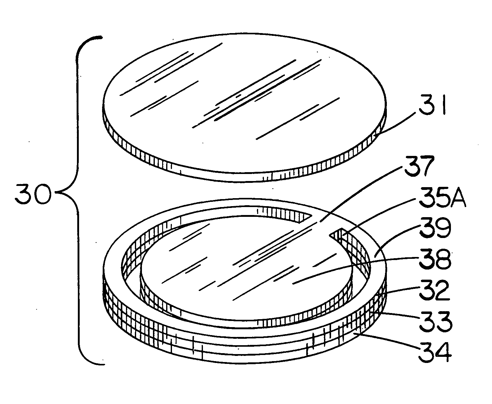
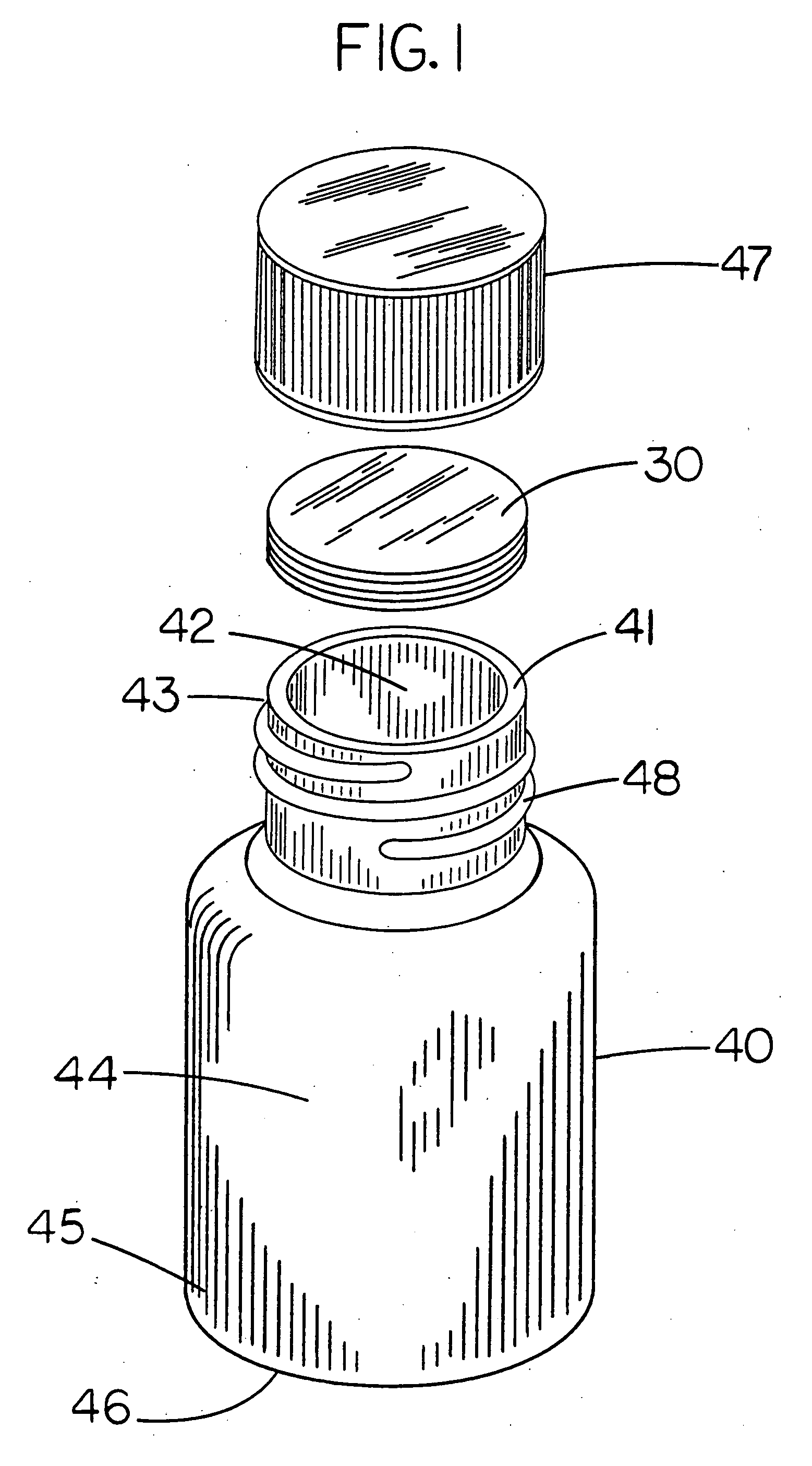
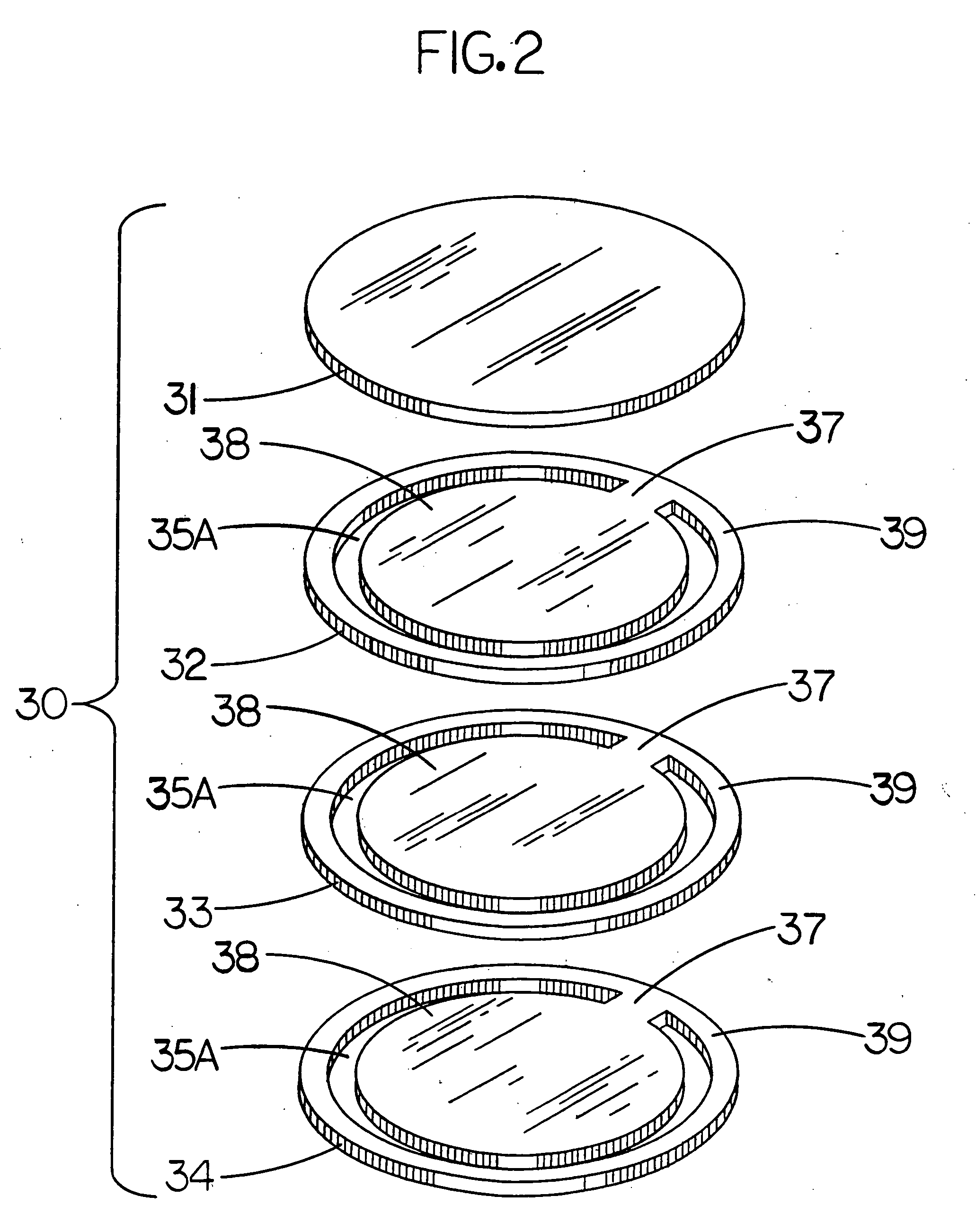
[0123] In this first embodiment adhesive layer 34 is comprised of a high strength, microencapsulated, reactive type adhesive to bond seal 30 to container 40 rim 41. Micro encapsulated adhesives are comprised of hollow spheres that can contain various types of single component, or two component adhesives such as resin and hardener. Seal 30 can be bonded to container 40 rim 41 by either melting the shell of the spheres during an induction sealing process, or the shells can be broken by the compression applied to rim contact portion 39 of seal 30 when closure cap 47 is installed. When the shell of the spheres are melted by heat or broken by compression, either a single component adhesive, or a two component adhesive that combines to initiate a curing reaction, bonds seal 30 to the container 40 rim 41. When fully dried or cured, hardened adhesive layer 34 creates a high strength bond that prevents rim contact portion 39 of seal 40 from being removed from rim 41 by force, or by the actio...

second embodiment

[0129] In this second embodiment adhesive layer 34 is comprised of a heat activated, high strength, hot melt type adhesive to bond seal 30 to container 40 rim 41. Heat generated in seal 30 during the installation process melts adhesive layer 34 which after cooling, bonds seal 30 to container 40 rim 41. When cooled, adhesive layer 34 creates a high strength bond that makes rim contact portion 39 of seal 30 resistant to surreptitious removal from rim 41 by force or by the action of solvents.

[0130] Although the use of this type of adhesive does not prevent seal 30 from being removed from rim 41 intact, and then replaced by the application of heat, it does provide a lower cost, tamper evident, pull open, leak proof seal 30 that can be used to seal containers 40 of ingestible and non ingestible products such as cosmetics, or skin cream etc. where product safety is also important.

[0131] Hot melt adhesives suitable for this purpose are widely used throughout the packaging industry and cos...

third embodiment

[0136] In this third embodiment, adhesive layer 34 is comprised of a heat activated, low strength, hot melt type adhesive to bond seal 30 to container 40 rim 41. Heat generated in seal 30 during the installation process melts adhesive layer 34, which after cooling, bonds seal 30 to container 40 rim 41. When cooled, adhesive layer 34 creates a low strength bond that is stronger than the strength of seal 30 in the area of breaking pattern 35A and, at the same time, weaker than the strength of pull tab 38 connector 37. When seal 30 is broken open and pull tab 38 is pulled, the low strength bond of adhesive layer 34 allows rim contact portion 39 of seal 30 to peel off container 40 rim 41 along with pull tab 38. Rim contact portion 39 remains attached to pull tab 38 which allows all of seal 30 to be completely removed from container 40 when pull tab 38 is pulled as further shown in FIG. 9.

[0137] Although using this weaker type of heat activated adhesive does not provide the same level of...


PUM


Abstract

A multi layered leak proof tamper evident container closure seal with an integral pull opener is constructed from a first layer of leak proof frangible sheet material that is adhesively bonded to a second layer of strengthening sheet material. The strengthening layer contains a varied C shaped cut out void configuration that forms a breaking pattern that turns the strengthening layer into a break and tear template layer. The adhesive layer bonding the frangible layer to the template includes an area void of the adhesive that duplicates the cut out void configuration of the breaking pattern. The seal is also bonded to the container rim without any adhesive being present in the area of the cut out void configuration of the breaking pattern thereby leaving only the single frangible layer covering over the C shaped cut out void configuration forming the breaking pattern which creates a weakness in the multi layered seal only in the area of the C shaped breaking pattern. When a consumer forces a finger into the installed seal the applied pressure forces the seal to break open and tear only in the weaker area of the C shaped breaking pattern configuration that follows in close proximity the inside perimeter of the container rim while the rim contact portion of the seal remains bonded to the container rim. The broken open C shaped central portion of the seal then forms a connected pull tab that can be lifted back out and pulled from the container. The ability of the seal to be easily broken open while the rim contact portion of the seal remains bonded to the container rim allows the seal to be bonded to the rim with either a strong adhesive that forces the pull tab to tear from the rim contact portion of the seal, or a weak adhesive that allows the rim contact portion of the seal to peel from the container rim along with the pull tab.

Description

[0001] Elements of the inventive concept disclosed in the specification contained herein also appear in my co-pending U.S. Patent application No. 03945 U.S. PTO Ser. No. 10 / 694,137 102703 Filed Oct. 27, 2003 and U.S. Patent application No. 22581 U.S. PTO Ser. No. 10 / 761,063 012004 Filed Jan. 20, 2004. FIELD OF THE INVENTION [0002] The invention resides in the area of container seals, specifically a tamper evident leak proof closure with an integral pull opener for sealing over the mouth opening of various types of rigid and semi rigid containers typically used for the storage and dispensing of a wide variety of consumer, commercial, and industrial products such as; ingestible products; food; health care products; personal care products; household products; or garage products and the like. BACKGROUND OF THE INVENTION [0003] A wide variety of consumer and commercial products such as; ingestible products; food; health care products; personal care products; household products; or garage...

Claims


Application Information

Patent Timeline
Patent Type & Authority Applications(United States)
IPC IPC(8): B65D51/20B65D53/00
CPCB65D53/04B65D51/20
Inventor JACKMAN, BRIAN FRANCIS
Owner JACKMAN BRIAN FRANCIS
Why Eureka
Try Eureka