Photodetector-amplifier circuit and optical pickup device

a technology of amplifier circuit and amplifier circuit, which is applied in the direction of photometry using electric radiation detectors, instruments, record information storage, etc., can solve the problems of unstable operation and inability to completely interrupt the path of the photodetector-amplifier circuit, and achieve the effect of stable operation

Active Publication Date: 2006-03-16
PANASONIC SEMICON SOLUTIONS CO LTD
View PDF15 Cites 55 Cited by
  • Summary
  • Abstract
  • Description
  • Claims
  • Application Information

AI Technical Summary

Benefits of technology

[0014] Therefore, an object of the present invention is to provide a photodetector-amplifier circuit and an optical pickup device which comprise a plurality of switchable photodetectors, an

Problems solved by technology

However, since the analog switch has a parasitic capacitance, a current path cannot be completely interrupted even when the switch is OFF.
Therefore, when a photoelectric current occurs by stray light entering a photodetector which is not connected to an operational amplifier, the ph

Method used


Image

  • Photodetector-amplifier circuit and optical pickup device
  • Photodetector-amplifier circuit and optical pickup device
  • Photodetector-amplifier circuit and optical pickup device

Examples


first embodiment

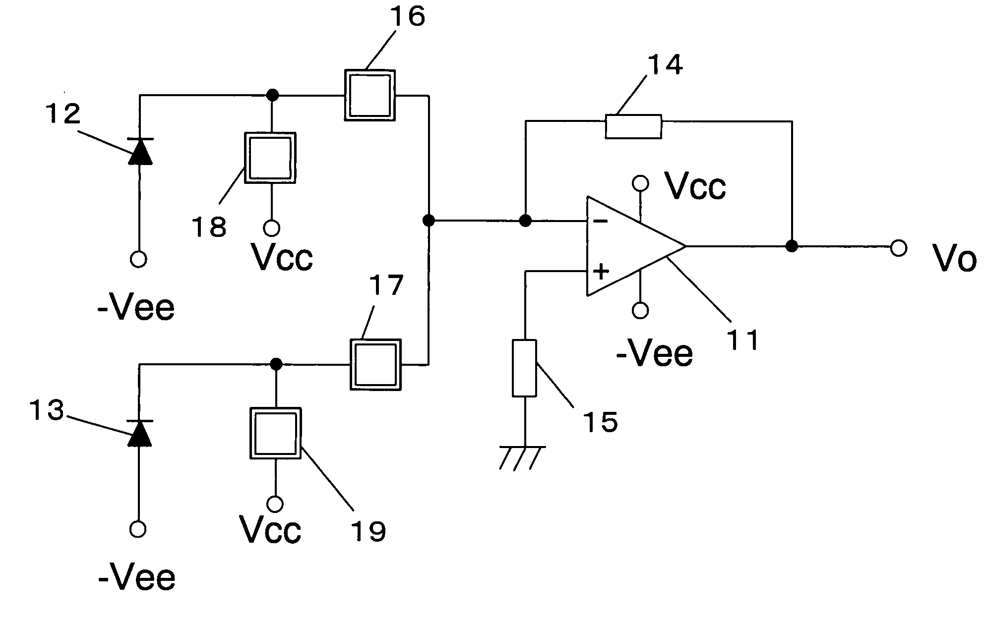
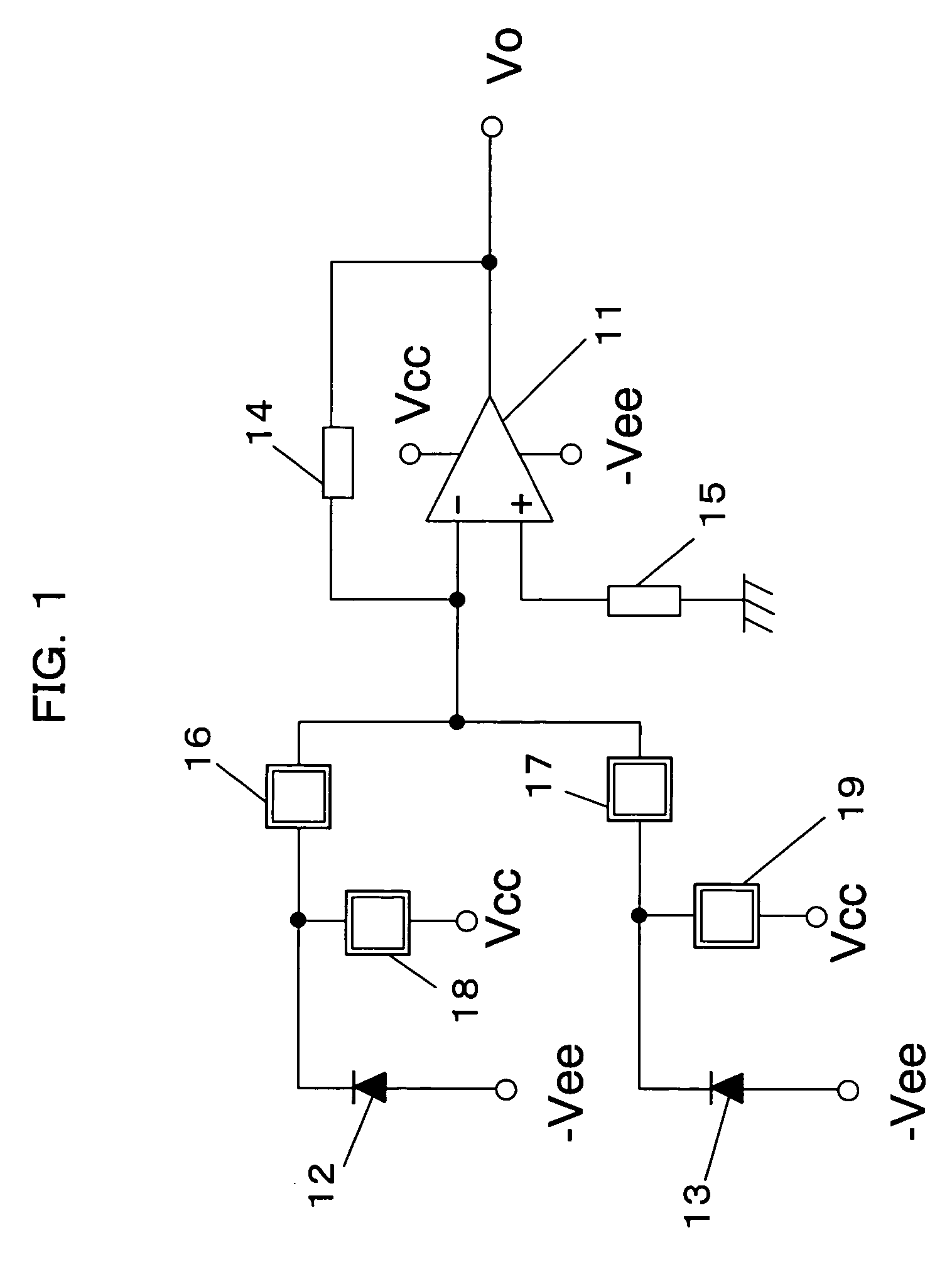
[0037]FIG. 1 is a diagram illustrating a photodetector-amplifier circuit according to a first embodiment of the present invention. The photodetector-amplifier circuit of FIG. 1 comprises an operational amplifier 11, photodetectors 12 and 13, switches 16 and 17, switches 18 and 19, a feedback resistor 14, and an impedance matching resistor 15.

[0038] The feedback resistor 14 is connected between an output terminal and an inverting input terminal (−) of the operational amplifier 11. The impedance matching resistor 15 is connected between a non-inverting input terminal (+) of the operational amplifier 11 and GND.

[0039] The photodetector 12 is connected via the switch 16 to the inverting input terminal (−) of the operational amplifier 11 and a negative voltage source Vee. A connection point between the photodetector 12 and the first switch 16 is connected via the switch 18 to a voltage source Vcc. The photodetector 13 is connected via the switch 17 to the inverting input terminal (−) o...

second embodiment

[0046]FIG. 3 is a diagram illustrating a photodetector-amplifier circuit according to a second embodiment of the present invention. The photodetector-amplifier circuit of the second embodiment has a basic structure similar to that of the first embodiment, and therefore, a difference therebetween will be hereinafter mainly described.

[0047] In the photodetector-amplifier circuit of FIG. 3, switches 18 and 19 are connected to a voltage source which is equal to an output offset voltage. More specifically, the switches 18 and 19 of the second embodiment are connected to GND.

[0048] According to the photodetector-amplifier circuit of the second embodiment, even when a switch 16 and the switch 18 are simultaneously turned ON, depending on a delay time between the switches 16 and 18 during the switching operation, a voltage input to an operational amplifier 11 at that moment is substantially equal to the output offset voltage. Therefore, at the moment when the switches 16 and 18 are simult...

third embodiment

[0050]FIG. 5 is a diagram illustrating an exemplary optical pickup device according to a third embodiment of the present invention. It is assumed that the optical pickup device 50 of the third embodiment supports two disc specifications DVD and CD for the sake of simplicity. Note that the optical pickup device of the third embodiment may be used in an optical disc drive apparatus supporting disc specifications other than DVD and CD.

[0051] The optical pickup device 50 of FIG. 5 comprises an infrared laser 51 which is a light source for CD and a red laser 52 which is a light source for DVD. Further, the optical pickup device 50 includes a 3-beam grating 53, beam splitters 54a and 54b, collimator lenses 55a and 55b, a mirror 56, an objective lens 57, and a light receiving IC 59.

[0052] Firstly, an operation of the optical pickup device of the third embodiment when an optical disc medium 58 is a CD will be described. Laser light emitted by the infrared laser 51 for CD is split into thr...


PUM


Abstract

The present invention provides a photodetector-amplifier circuit capable of eliminating an influence of noise due to stray light entering a non-selected photodetector to stably select and switch a photodetector. The photodetector-amplifier circuit of the present invention comprises photodetectors 12 and 13. The photodetector 12 is connected via a switch 16 between an inverting input terminal of an operational amplifier 11 and GND, and is also connected via a switch 18 to a voltage source Vcc. The photodetector 13 is connected via a switch 17 to the inverting input terminal of the operational amplifier 11 and GND, and is also connected via a switch 19 to the voltage source Vcc.

Description

BACKGROUND OF THE INVENTION [0001] 1. Field of the Invention [0002] The present invention relates to a photodetector-amplifier circuit and an optical pickup device. More particularly, the present invention relates to a photodetector-amplifier circuit and an optical pickup device which can switch a plurality of photo-detecting sections.[0003] 2. Description of the Background Art [0004] Recently, as the packaging density, function, and operating speed of semiconductor integrated circuits have been improved, technology has also been developed in which a semiconductor integrated circuit is composed of a plurality of function circuits, and a function circuit to be operated is selected by switching ON or OFF a current supplied to each function circuit. [0005] As an example of such technology, a photodetector-amplifier circuit will be described which is used in an optical pickup device of an optical disc drive to read a signal from an optical disc medium. [0006] Optical disc drive apparatu...

Claims


Application Information

Patent Timeline
IPC IPC(8): G01J1/42G11B7/13
CPCG11B7/13G01J1/44
Inventor MIYAMOTO, SHINICHIFUKUDA, HIDEO
Owner PANASONIC SEMICON SOLUTIONS CO LTD
Why Eureka
Try Eureka