

Fault tolerant homopolar magnetic bearings
- Summary
- Abstract
- Description
- Claims
- Application Information
AI Technical Summary
Benefits of technology
Problems solved by technology
Method used
Image

Examples
examples
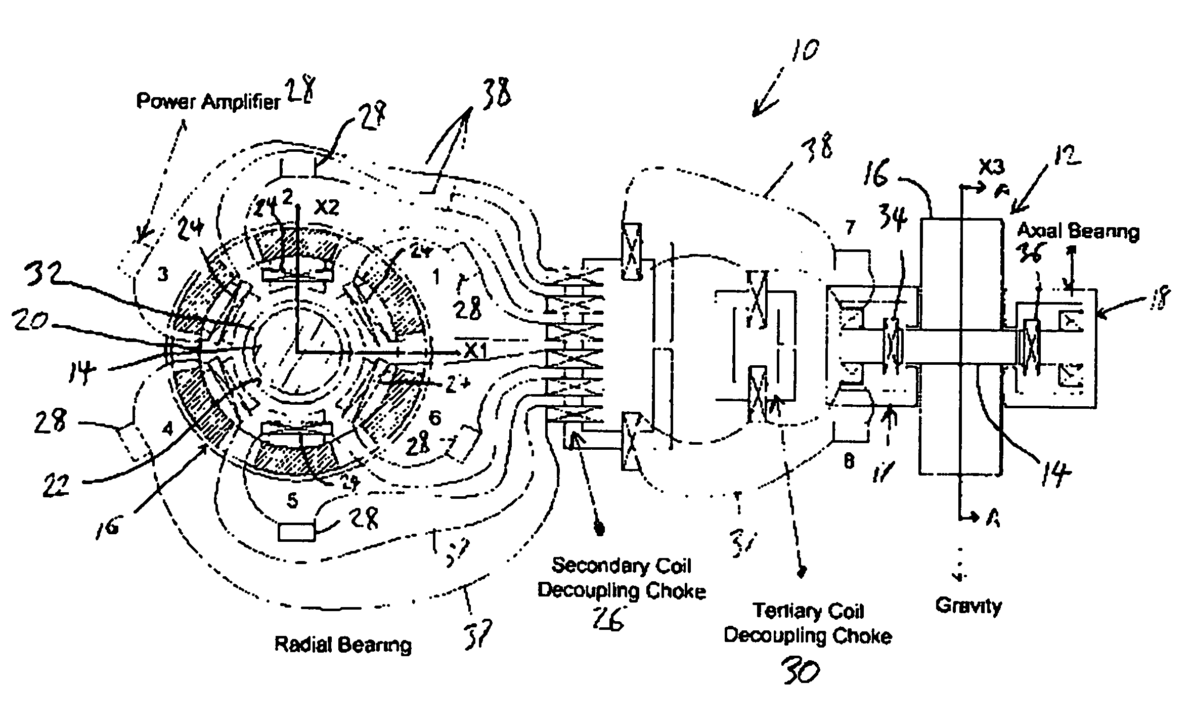
[0046] An example flywheel module illustrates operation and reliability of the redundant magnetic suspension. Table 1 lists the geometrical, inertia and stiffness parameters for the model. A suitable catcher bearing contact model can have a stiffness of 108 (N / m), a damping of 5,000 (N-s / m) and a dynamic friction coefficient of 0.1. Table 2 shows the magnetic bearing parameters for the MS model.
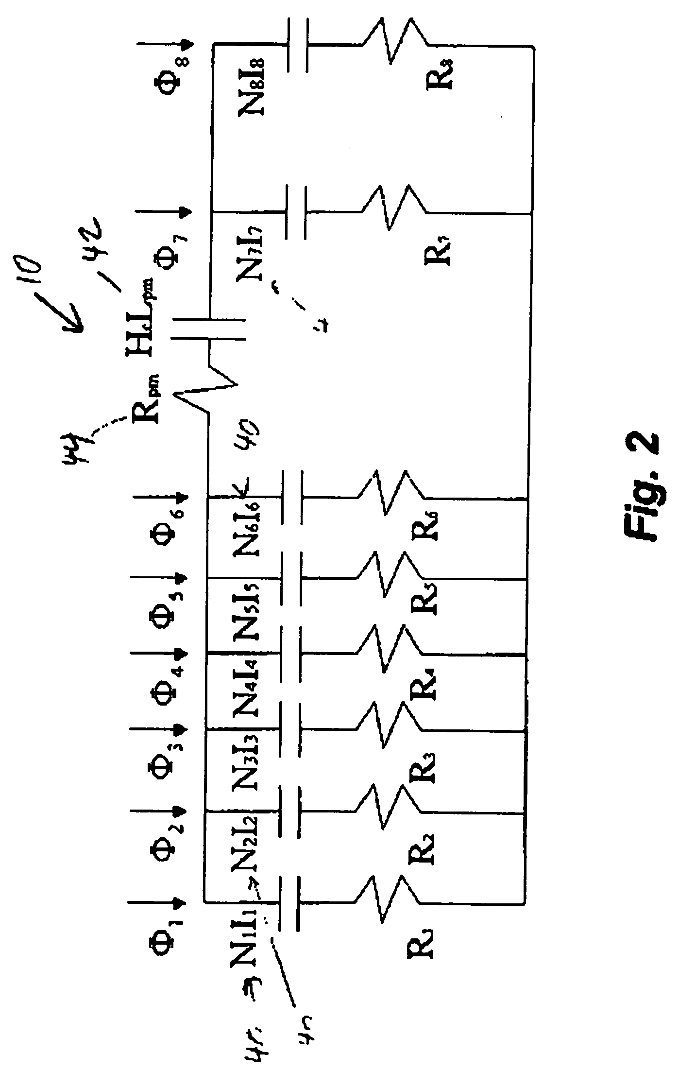
[0047] The 1D magnetic circuit model shown in FIG. 2 must be adjusted to include the effects of recirculation leakage of the flux between the N and S poles of any permanent magnet and for the effect of non-parallel (fringing) flux flow in the air gap of each pole. These adjustments are made with multiplicative factors applied to the gap flux and permanent magnetic (PM) coercive force in the 1D model, as derived from the 3D FE model. The PM coercive force is derated from 950,000 to 514,000 in the combo bearing and from 950,000 to 566,000 in the radial bearing. The air gap 22 fluxes are derate...
PUM
 Abstract
Description
Claims
Application Information