Diffractive lenses for vision correction

a technology of diffractive lenses and vision correction, applied in the field of diffractive lenses for vision correction, can solve the problems of not providing two different focal distances, e.g., near and distant, and achieve the effects of reducing the cost of application, avoiding undesirable irritation, and being easy to manufactur

Active Publication Date: 2006-03-16
APOLLO OPTICAL SYST
View PDF90 Cites 103 Cited by
  • Summary
  • Abstract
  • Description
  • Claims
  • Application Information

AI Technical Summary

Benefits of technology

[0009] Briefly described, the present invention embodies a lens having a first diffractive structure, referred to herein as a wavefront splitting diffractive structure (WSD), for splitting light into two or more diffractive orders to different focus distances or ranges, and a second diffractive structure, referred to as a multiorder diffractive structure (MOD), for diffracting light of different wavelengths in a plurality of different diffractive orders to a common focus distance or range. The first and second diffractive structures in combination provide the lens with at least distance and near vision correction. The first and second diffractive structures may be combined on the same surface or located on different surfaces of the lens. Thus, light incident the lens is diffracted by the first diffractive structure and then by the second diffractive structure, or vice versa depending on the order of such structures in the lens, or by a single diffractive structure of the lens having a profile that combines the first and second diffractive structures.
[0013] Optionally, an optical element, such as a substrate or coating, may be provided on the surface having the MOD structure to provide a smooth outer surface.
[0020] The lenses of the present invention may be used in a variety of ophthalmic applications, such as a contact lens, a spectacle lens, or the lens of an intraocular implant (IOL), or other optics useful for vision correction of the eye. In the contact lens application, it is advantageous to use of a WSD structure that is a sinusoidal harmonic, since the edges of the structure are so smooth that the structure can be located directly on the lens' surface which will contact the eye (or the inner eye lid), and thus worn comfortably by the contract lens user without undesirable irritation that would otherwise be caused by the presence of sharp edges. Further, a lens having such a sinusoidal harmonic WSD structure can be easier to manufacture and at lower cost in application since the surface does not require to be smoothed by addition of coatings or substrates.

Problems solved by technology

The MOD lenses correct for this problem, but does not provide two different focal distances, e.g., near and distant, useful for providing therapeutic bifocal corrective ophthalmic lenses.

Method used


Image

  • Diffractive lenses for vision correction
  • Diffractive lenses for vision correction
  • Diffractive lenses for vision correction

Examples


example 1

[0054] In this example, an ophthalmic lens prescription requires a correction of −7 diopters (D) for distance vision, with a +2 diopters (D) add power for near vision. Thus, the two powers (denoted by φ) of the lens are

φdistance=−7D

φnear=−5D(=−7D+2D=φdistance+φadd)

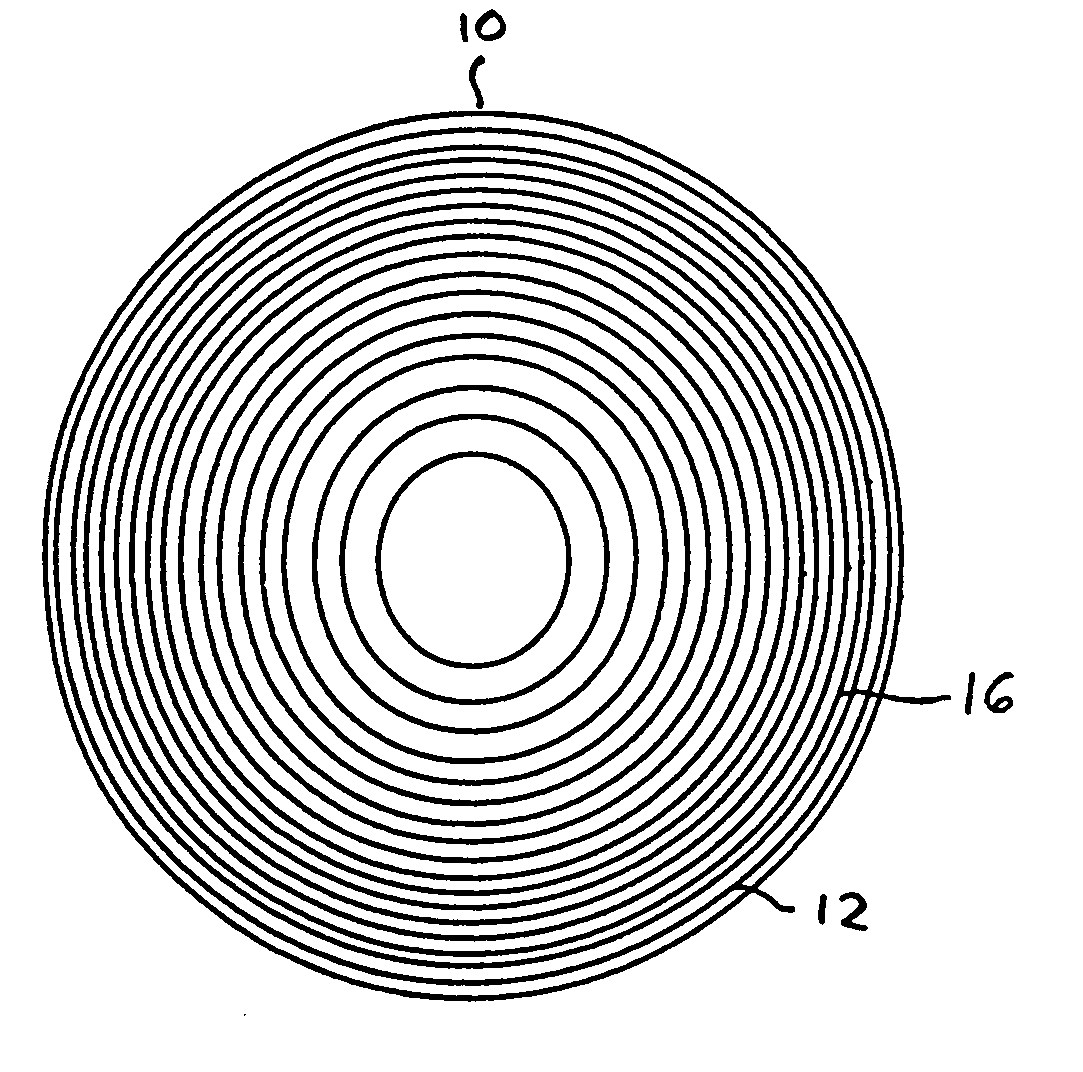
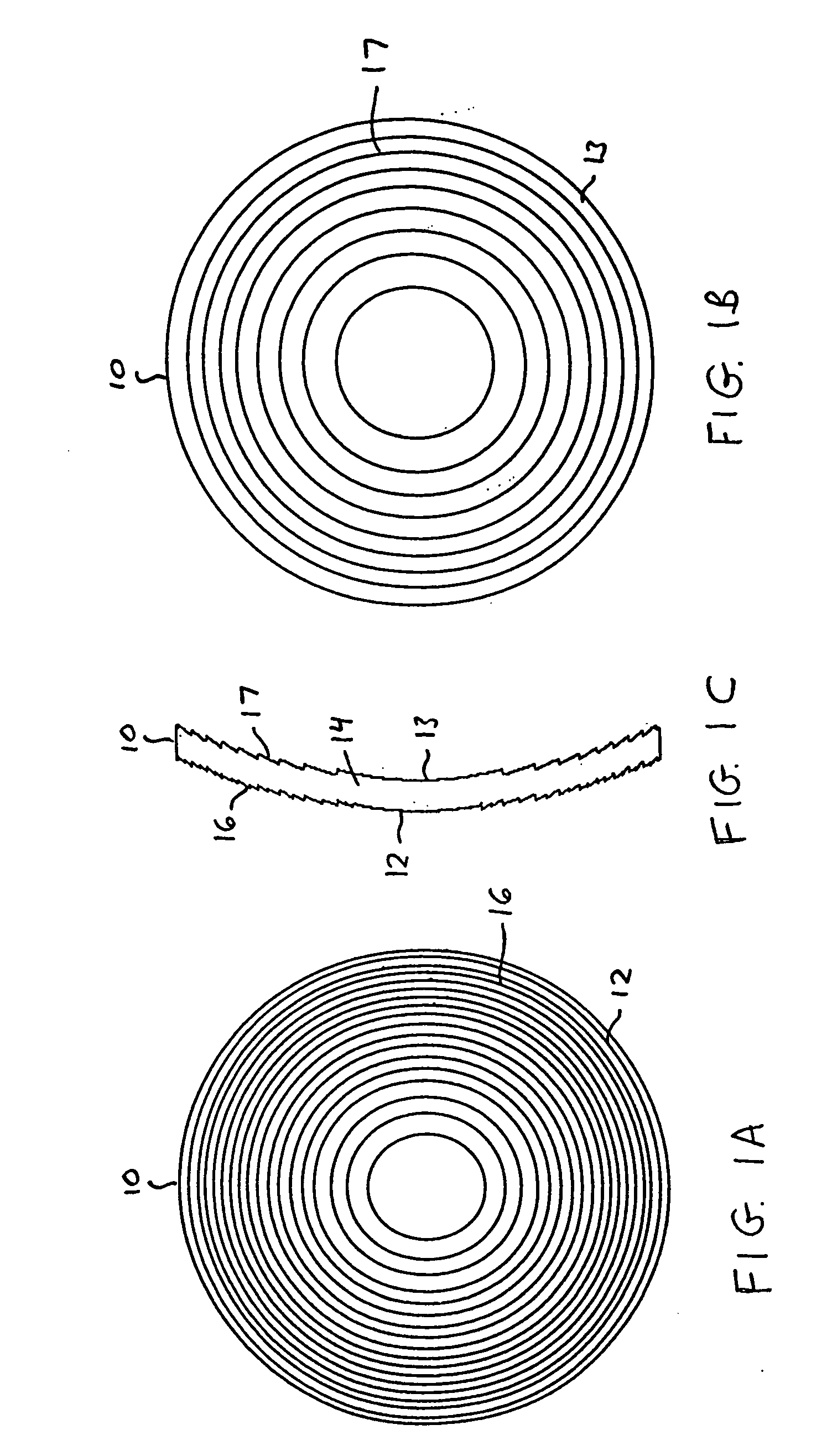
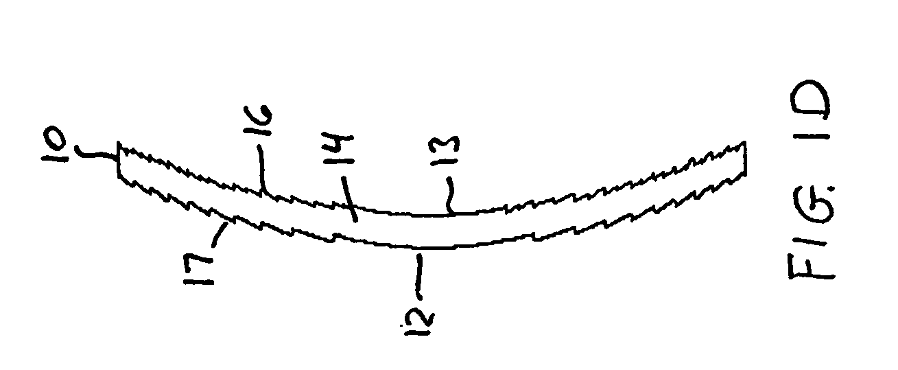
The lens will consist of a MOD structure 17 with the required distance power on one side (i.e., along surface 12 or 13) of a thin substrate providing the lens body 14, and with a WSD structure 16 with a blazed surface, operating primarily in the 0 and +1 orders, on the other side (or surface).

[0055] The radial locations (rj) of the diffractive zones of the MOD structure are given by rj=2⁢j⁢ ⁢p⁢ ⁢λ0ϕdistance

[See Equation (1) of incorporated U.S. Pat. No. 5,589,982, with φ0=1 / F0.]

[0056] In this example, the selected design wavelength λ0=555 nm (peak of photopic response). The photopic response refers to the efficiency of the human eye's perception of light wavelengths under high illumination. If p=10, the zone radii w...

example 2

[0061] This example has the same ophthalmic prescription (−7 D distance power, with a +2 D add power) as Example 1, but uses a WSD structure 16 having a square-wave diffractive surface. The square-wave surface introduces one-half wavelength of optical path difference (OPD) (or, equivalently, a phase shift of π radians) over half of each zone and zero OPD over the remaining half of the zone. Since the square-wave diffractive surface has appreciable energy in the +1 and −1 diffraction orders, the power of the MOD structure in this case is φMOD=−6 D and the power of the square-wave WSD surface is φSQW=+1 D. The resulting total lens powers are, as in the previous example

φdistance=φMOD−φSQW=−6D−1D=−7D

φnear=φMOD+φSQW=−6D+1D=−5D=φdistance+φadd

The radial locations (rj) of the diffractive zones of the MOD structure are given by rj=2⁢j⁢ ⁢p⁢ ⁢λ0ϕMOD

[0062] Again, the selected design wavelength λ0=555 nm (peak of photopic response). If p=10, the zone radii within a clear aperture diameter o...


PUM


Abstract

Diffractive lenses for vision correction are provided on a lens body having a first diffractive structure for splitting light into two or more diffractive orders to different focal distances or ranges, and a second diffractive structure, referred to as a multiorder diffractive (MOD) structure, for diffracting light at different wavelengths into a plurality of different diffractive orders to a common focal distance or range. In a bifocal application, the first and second diffractive structures in combination define the base power for distance vision correction and add power for near vision correction of the lens. The first and second diffractive structures may be combined on the same surface or located on different surfaces of the lens. The first diffractive structure may have blazed (i.e., sawtooth), sinusoidal, sinusoidal harmonic, square wave, or other shape profile. A sinusoidal harmonic diffractive structure is particularly useful in applications where smooth rather than sharp edges are desirable.

Description

[0001] This is a continuation-in-part of U.S. patent application Ser. No. 10 / 922,600, filed Aug. 20, 2004.FIELD OF THE INVENTION [0002] The present invention relates to diffractive lenses for vision correction, and particularly to diffractive lenses for therapeutic vision correction at at least distance and near vision correction suitable for use with a variety of vision correction applications, such as intraocular implants (IOLs), contact lenses, or spectacle (eyeglass) lenses. The invention further relates to a method for providing such diffractive lenses. BACKGROUND OF THE INVENTION [0003] Multiorder diffractive (MOD) lenses are useful for bringing a plurality of spectral components of different wavelengths to a common focus, and are described in U.S. Pat. No. 5,589,982. The MOD lens has a structure of multiple annular zones having step heights defining zone boundaries, which diffract light at different wavelengths into different diffractive orders to a common focus. In contrast,...

Claims


Application Information

Patent Timeline
Patent Type & Authority Applications(United States)
IPC IPC(8): G02C7/06
CPCA61F2/1613A61F2/1618A61F2/1648A61F2/1654G02B3/08G02C7/044G02C7/028G02C7/042G02C7/06G02C2202/20G02B5/1895A61F2/16G02C7/02G02C7/04
Inventor MORRIS, G. MICHAELBURALLI, DALE A.FEDERICO, RICHARD J.
Owner APOLLO OPTICAL SYST
Why Eureka
Try Eureka