
Laser production technology for radio frequency identification antenna capable of easily discharging waste

A radio frequency identification and production process technology, applied in the field of electronic radio frequency identification, can solve the problems such as the reduction of the bonding strength of the antenna metal film and the substrate, the requirements of the antenna production environment, and the increase of the cost of raw materials, etc., and achieves good waste discharge effect and consistency. Good, takes up less space

Active Publication Date: 2016-07-20
SUZHOU ZUENS IOT TECH CO LTD
View PDF3 Cites 15 Cited by
  • Summary
  • Abstract
  • Description
  • Claims
  • Application Information

AI Technical Summary

Problems solved by technology

To improve the contrast, usually use dark ink pigments and increase the content of pigments in the ink or adhesive, resulting in the problem of color penetration on the back of light weight paper substrates, which is detrimental to the visual effect of printing and printing on the back of paper substrates At the same time, the increase of the pigment content will reduce the solid content of the resin used for bonding in the ink, which will result in a decrease in the bonding strength between the antenna metal film and the substrate
In addition, there is a solution to use phosphor powder instead of pigment, but the use of phosphor powder will increase the cost of raw materials, and it is usually not applicable to pharmaceuticals, food and other industries, and there are special requirements for the lighting of the antenna production environment

Method used


Image

  • Laser production technology for radio frequency identification antenna capable of easily discharging waste
  • Laser production technology for radio frequency identification antenna capable of easily discharging waste
  • Laser production technology for radio frequency identification antenna capable of easily discharging waste

Examples


Embodiment Construction

[0071] The technical solutions in the embodiments of the present invention will be described clearly and completely below. Obviously, the described embodiments are only a part of the embodiments of the present invention, rather than all the embodiments. Based on the embodiments of the present invention, all other embodiments obtained by those of ordinary skill in the art without creative work shall fall within the protection scope of the present invention.

[0072] See Figure 1-23 , The embodiment of the present invention includes:

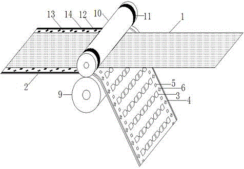
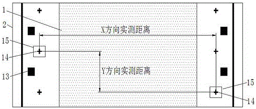
[0073] An easy-to-discharge radio frequency identification antenna laser production process. According to the position and distance of the positioning mark in the X and Y directions, the change value is compared with the standard value. According to the change value, substrate material, temperature, humidity and antenna layout, use The software performs adaptive transformation or pre-processing of the laser engraved graphics, so that the edge of the ...


PUM

PropertyMeasurementUnit
shrinkageaaaaaaaaaa
shrinkageaaaaaaaaaa

Abstract

The invention discloses a laser production technology for a radio frequency identification antenna capable of easily discharging waste. In the laser production technology for the radio frequency identification antenna, changes of positions and dimensions of positioning marks at two sides of a radio frequency antenna substrate in X and Y directions are detected; real-time transformation is carried out on the shape, the dimension, the position and the angle of an engraved pattern through an adaptive algorithm according to the materials, the thicknesses, the composite temperatures, the environment temperatures and the humidities of a used metal film and the antenna substrate and the antenna design pattern and composition condition; meanwhile, laser engraving is compensated according to the monitored working temperature in a laser scanning system; and the influence of a temperature drift of the laser scanning system on the dimension and the position of the engraved pattern is reduced, so that the error of the system for overlapping positioning of the engraved pattern and a printed pattern is controlled within 20 microns or to be smaller than 1 / 2 laser spot size; the waste discharge technology is relatively easy to implement; the key problems of pattern positioning and edge tracking in the industrial process of the laser production technology for the radio frequency identification antenna are solved; and the industrialization process of the laser antenna production technology is pushed.

Description

Technical field [0001] The invention relates to the field of electronic radio frequency identification, in particular to a laser production process of a radio frequency identification antenna which is easy to discharge waste. Background technique [0002] At present, more than 90% of RFID tag antennas are produced by etching process, and a small part is produced by silver paste printing, vacuum sputtering, and vacuum coating. However, the etching produces a large amount of waste liquid and exhaust gas which brings environmental pollution problems, the high cost of silver paste printed antennas, and the poor electrical performance and reliability of vacuum sputtering and coating antennas. A new process is needed to overcome the shortcomings of the above process, and the current RFID tag antenna laser production process is the main development direction. [0003] In the laser production process of RFID antennas, the positioning and alignment accuracy of the laser engraved graphics a...

Claims


Application Information

Patent Timeline
Patent Type & Authority Applications(China)
IPC IPC(8): H01Q1/38B23K26/362B23K26/082
CPCB23K26/082B23K26/361H01Q1/38
Inventor 陆凤生张金松
Owner SUZHOU ZUENS IOT TECH CO LTD
Learn More