Imaging material wih improved contrast

a technology of image contrast and light transmission, applied in the direction of optics, projectors, instruments, etc., can solve the problems of reducing contrast, reducing image contrast, and diffusive elements, so as to reduce backscatter, reduce image contrast, and reduce speckle

Inactive Publication Date: 2006-03-16
MASSACHUSETTS DEV FINANCE AGENCY
View PDF4 Cites 16 Cited by
  • Summary
  • Abstract
  • Description
  • Claims
  • Application Information

AI Technical Summary

Benefits of technology

[0009] The present invention addresses a need in the art for an imaging material that provides reduced backscatter, low speckle contrast and high image contrast in a thin form factor;

Problems solved by technology

Imaging screens such as those used in rear projection typically have a diffusive element that has an undesirable level of backscatter that reduces contrast, especially in high ambient light situations.
These diffusive elements significantly scatter ambient light back towards the viewer which reduces the contrast of the image.
Such diffusion layers cannot be placed behind the black stripes because to do so would reduce the resolution of the imaging process used to produce those black stripes.
Placing the diffusion layer behind the black stripes would also result in a loss of quality and definition of the edge of the black stripe.
Also, by adding a diffusive element on the viewer side of the black stripe region, the thickness and cost of the screen is increased.
Therefore, when trying to reach a specific horizontal and vertical viewing angle target, it is likely that the viewing angle in the opposite direction is not optimized and this decreases the gain of the screen over the desired viewing angles.
This reduces the image contrast of the display in ambient light conditions.
This often introduces spurious interfacial reflections at the elemen

Method used


Image

  • Imaging material wih improved contrast
  • Imaging material wih improved contrast
  • Imaging material wih improved contrast

Examples


example 1

[0116] A projection screen, in accordance with the present invention, can be produced as described in FIG. 18, that is designed to have increased ambient light absorption and increased gain. This is possible because the diffusion in the vertical plane is achieved by an asymmetric diffuser located before the black stripe region. This enables a diffuser added on the viewer side of the black stripe region to have reduced diffusion angles, and as a result, less backscatter. The additional diffuser also reduces the speckle contrast.

[0117] A comparative sample for reference to prior art was first made. Sample S1 was made by first index matching a lenticular lens from Reflexite Corporation to a photopolymer film Cromalin™ from DuPont using an index matching fluid with a refractive index of 1.51. The Cromalin™ was exposed through the lenticular lens by collimated UV light. Toner was then applied to the sample achieving a black stripe pattern. A symmetric diffuser with a FWHM of 16 degrees ...

example 2

[0121] A projection screen, in accordance with the present invention, can be produced as described in FIG. 18, that is designed to have increased ambient light absorption and increased gain. This is possible because the diffusion in the vertical plane is achieved by an asymmetric diffuser located before the black stripe region. This enables the diffuser on the viewer side of the black stripe region to have reduced diffusion angles, and as a result, less backscatter.

[0122] Sample A2 was made by first creating an asymmetric diffuser with a FWHM of 18 degrees by 6 degrees and gain of 44 by dispersing 30% by weight polyethylene particles with a refractive index of 1.51 within a matrix material of polyester with a refractive index of 1.568 and stretching the material as described in U.S. Pat. No. 5,932,342. This asymmetric diffuser was index matched to a lenticular lens from Reflexite Corporation to using an index matching fluid with a refractive index of 1.51. A photopolymer film Croma...

example 3

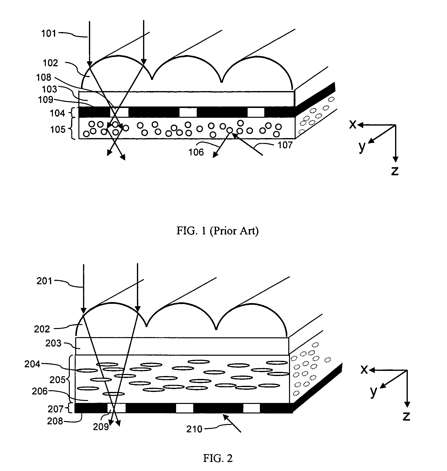
[0125] A projection screen, in accordance with the present invention, can be produced as described in FIG. 2, that is designed to have increased ambient light absorption and increased gain. This is possible because the diffusion in the vertical plane is achieved by an asymmetric diffuser located before the black stripe region. By eliminating the need for a second diffuser on the viewer side of the black stripe region, the ambient light absorption is improved.

[0126] Sample A3 was made by first creating an asymmetric diffuser with a FWHM of 18 degrees by 6 degrees and gain of 44 by dispersing 30% by weight polyethylene particles with a refractive index of 1.51 within a matrix material of polyester with a refractive index of 1.568 and stretching the material as described in U.S. Pat. No. 5,932,342. This asymmetric diffuser was index matched to a lenticular lens from Reflexite Corporation to using an index matching fluid with a refractive index of 1.51. A photopolymer film Cromalin™ fr...


PUM


Abstract

An imaging material has been developed which provides improved image contrast, increased gain and increased viewing angle. A method for production of the screen element is also described. The imaging material of the invention includes a refractive optical element which redirects incident light along a desired axis, a light transmissive focusing region which diffuses the light along the desired axis, and a controlled light-transmissive region which controls backscatter and increases contrast. The refractive optical element desirably includes an active surface such as a lenticular array embossed thereon which serves to redirect incident light as desired. The focusing region desirably is made of a matrix material having a refractive index n1, having dispersed throughout the matrix asymmetric micro-bodies that have a refractive index n2 different from n1. The controlled light-transmissive region may desirably comprise an alternating black stripe and transparent region. Various implementations of these elements of course are contemplated as within the scope of the invention The materials described herein are typically used in a rear and/or front projection display system such as those used in televisions, computers, home theatres, information displays and simulation systems.

Description

RELATED APPLICATIONS [0001] This application claims the benefit of priority under 35 U.S.C. 119(e) to pending U.S. Provisional Application No. 60 / 600,403, filed on Aug. 10, 2004 as Docket No. 28596-002 PRO; and pending U.S. Application No. 60 / 598826, filed on Aug. 4, 2005 as Docket No. 28596-001; the entire contents of which are incorporated herein by reference.FIELD OF THE INVENTION [0002] The invention generally relates to the design of a light transmitting screen element, and methods of manufacture, and more specifically its use in a rear and / or front projection display system, and liquid crystal displays (LCDs), such as those used in televisions, computers, home theatres, information displays and simulation systems. BACKGROUND OF THE INVENTION [0003] Imaging screens such as those used in rear projection typically have a diffusive element that has an undesirable level of backscatter that reduces contrast, especially in high ambient light situations. Traditional rear projection sc...

Claims


Application Information

Patent Timeline
IPC IPC(8): G03B21/56
CPCG03B21/625G03B21/602
Inventor YEO, TERENCE E.COLEMAN, ZANE A.
Owner MASSACHUSETTS DEV FINANCE AGENCY
Why Eureka
Try Eureka