
Accelerated video encoding using a graphics processing unit

Active Publication Date: 2006-03-16
MICROSOFT TECH LICENSING LLC
View PDF33 Cites 95 Cited by
  • Summary
  • Abstract
  • Description
  • Claims
  • Application Information

AI Technical Summary

Benefits of technology

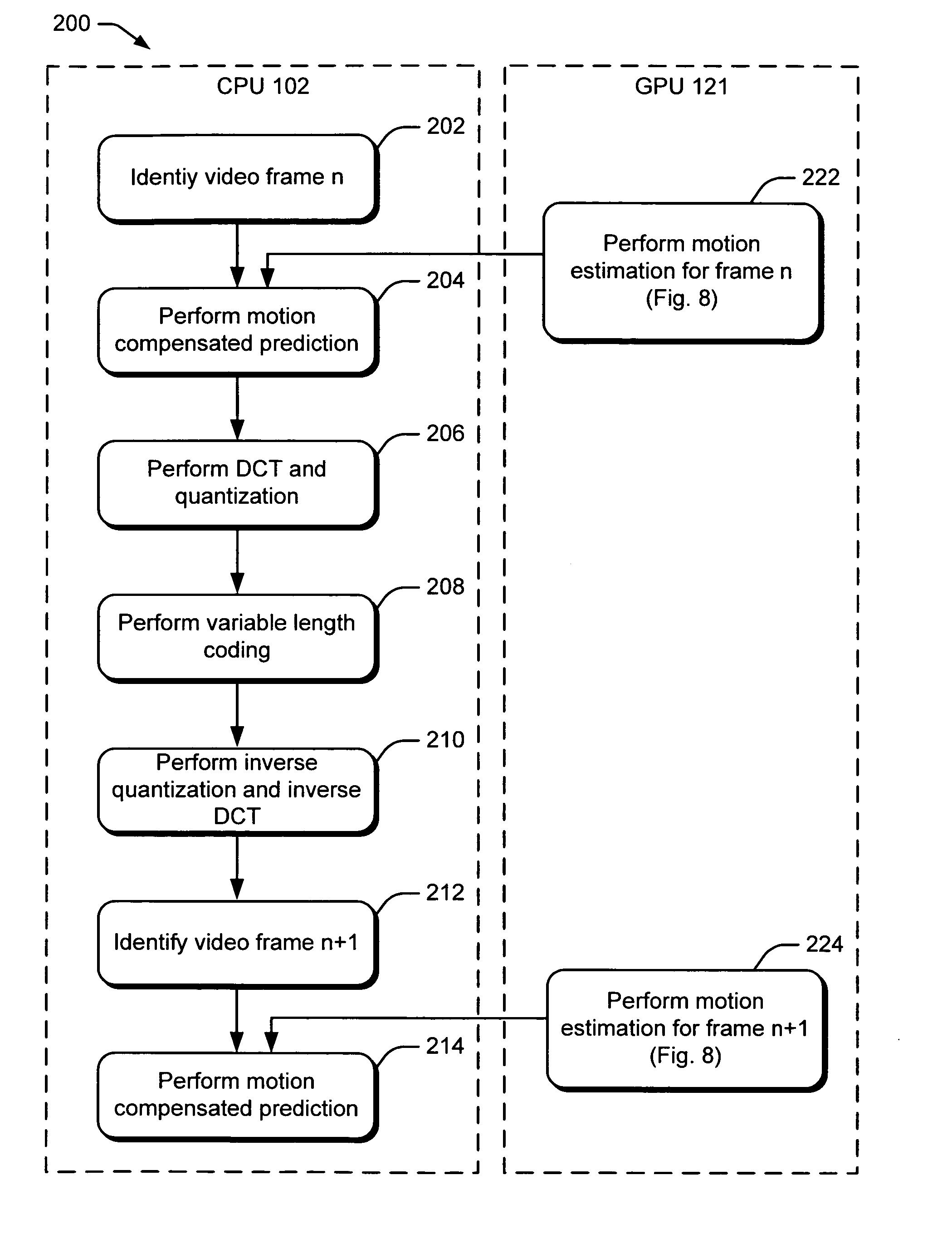
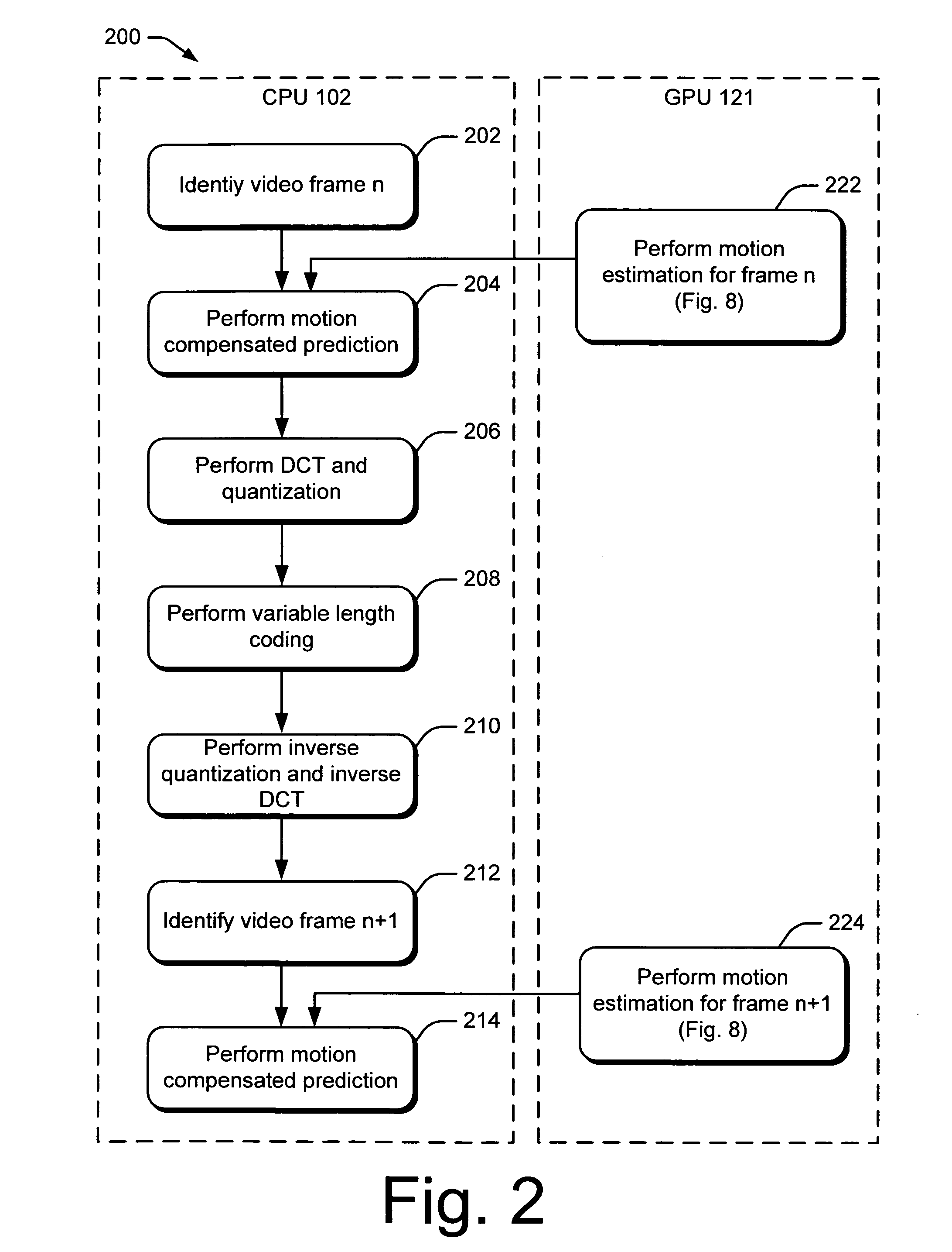
[0005] The systems and methods described herein are directed at accelerating video encoding using a graphics processing unit. In one aspect, a video encoding system uses both a central processing unit (CPU) and a graphics processing unit (GPU) to perform video encoding. The system implements a technique that enables the GPU to perform motion estimation for video encoding. The technique allows the GPU to perform a motion estimation process in parallel with the video encoding process performed by the CPU. The performance of video encoding using such a system is greatly accelerated as compared to encoding using just the CPU.
[0006] In another aspect, data related to motion estimation is arranged and provided to the GPU in a way that utilizes the capabilities of the GPU. Data about video frames may be collocated to enable multiple channels of the GPU to process tasks in parallel. The depth buffer of the GPU may be used to consolidate repeated calculations and searching tasks during the motion estimation process. The use of frame collocation and depth buffer enables the GPU to be better utilized and to further accelerate video encoding.

Problems solved by technology

Encoding digital multimedia content typically requires significant amount of processing power, especially for real-time applications.
In particular, video encoding is computationally intensive and typically requires a computer to have a fast central processing unit (CPU).
In video encoding, motion estimation is often the most complex process.
Accordingly, because the computational complexity of motion estimation is high, motion estimation occupies a significant portion of the processing power and resources that are needed for the whole encoding process and is usually the bottleneck.

Method used


Image

  • Accelerated video encoding using a graphics processing unit
  • Accelerated video encoding using a graphics processing unit
  • Accelerated video encoding using a graphics processing unit

Examples


Embodiment Construction

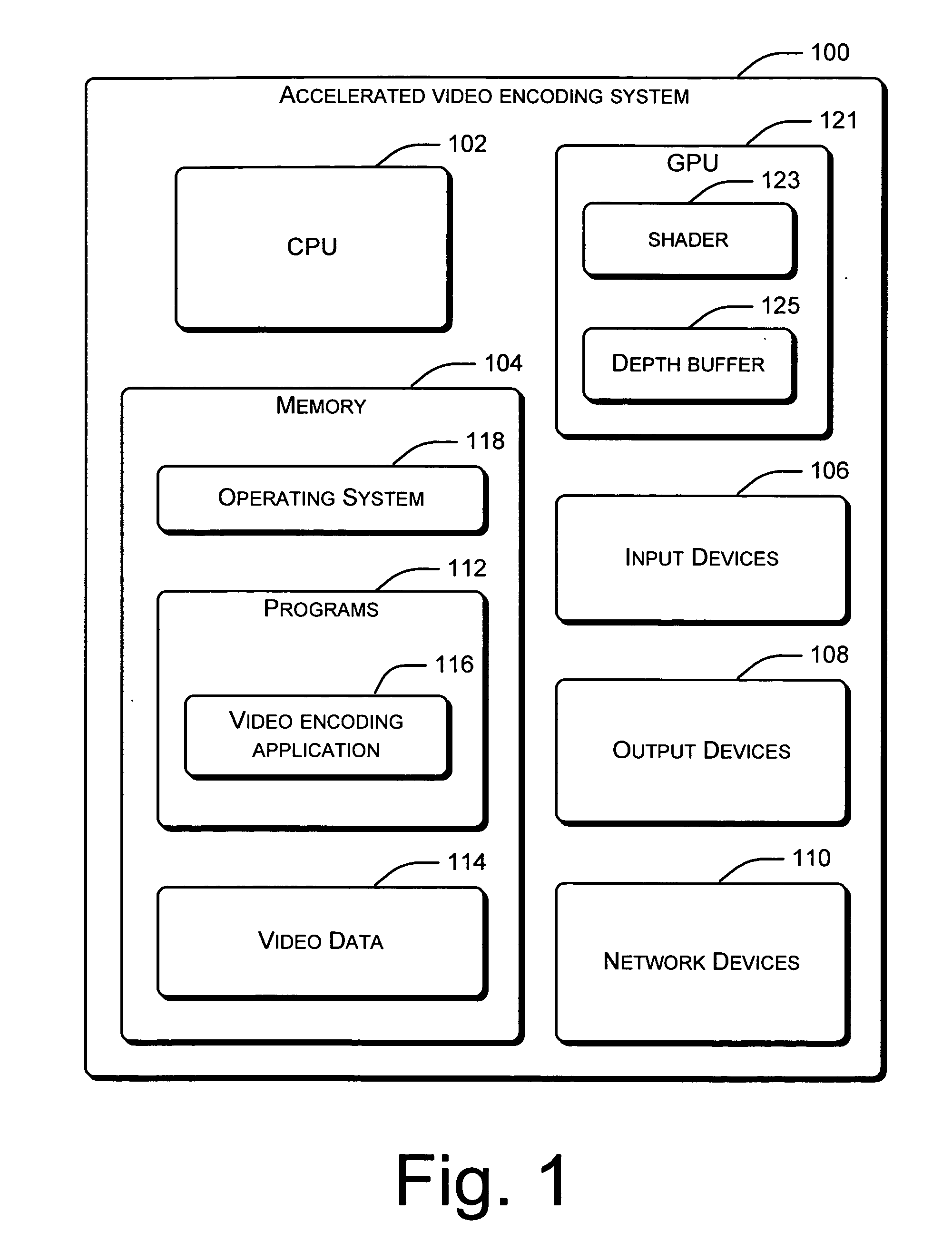
[0022] The processing power of graphics processing units (GPUs) has been increasing much faster than that of central processing units (CPUs). Computers are increasing equipped with high performance GPUs. The described systems and methods utilize the processing power of GPU to handle motion estimation. In order to use a GPU to accelerate video encoding, a different video encoding architecture is needed such that the CPU and the GPU can be operated in parallel. An example of such architecture is described below.

[0023]FIG. 1 illustrates accelerated video encoding system 100 within which the described systems and methods can be either fully or partially implemented. Accelerated video encoding system is only one example of a computing system and is not intended to suggest any limitation as to the scope of the use or functionality of the invention.

[0024] Accelerated video encoding system 100 is configured to receive video signal from a variety of sources. Accelerated video encoding syst...


PUM


Abstract

A video encoding system uses both a central processing unit (CPU) and a graphics processing unit (GPU) to perform video encoding. The system implements a technique that enables the GPU to perform motion estimation for video encoding. The technique allows the GPU to perform a motion estimation process in parallel with the video encoding process performed by the CPU. The performance of video encoding using such a system is greatly accelerated as compared to encoding using just the CPU. Also, data related to motion estimation is arranged and provided to the GPU in a way that utilizes the capabilities of the GPU. Data about video frames may be collocated to enable multiple channels of the GPU to process tasks in parallel. The depth buffer of the GPU may be used to consolidate repeated calculations and searching tasks during the motion estimation process.

Description

CROSS-REFERENCE TO RELATED APPLICATIONS [0001] The present application is a continuation of U.S. patent application Ser. No. 10 / 939,983 filed September 13, 2004.TECHNICAL FIELD [0002] The systems and methods discussed herein relate to video processing and, in particular, to accelerated video encoding. BACKGROUND OF THE INVENTION [0003] Encoding digital multimedia content typically requires significant amount of processing power, especially for real-time applications. In particular, video encoding is computationally intensive and typically requires a computer to have a fast central processing unit (CPU). In video encoding, motion estimation is often the most complex process. Motion estimation refers to the process of finding the best prediction for a block in the current frame from a previously encoded reference frame(s). Motion estimation is commonly conducted via searching. To capture the real motion for better prediction and visual quality, the search range cannot be very small. A...

Claims


Application Information

Patent Timeline
IPC IPC(8): H04N11/02H04N11/04H04N7/12H04B1/66G06T7/20G06T15/00H03M7/36H04N19/50H04N19/60
CPCH04N21/4143H04N19/56H04N19/557H04N19/43H04N19/436H04N19/42
Inventor SHEN, GUOBINLI, SHIPENGGAO, GUANGPING
Owner MICROSOFT TECH LICENSING LLC
Learn More