
Method and apparatus for determining offsets of a part from a digital image

Inactive Publication Date: 2006-03-16
HOLMES DAVID
View PDF19 Cites 99 Cited by
  • Summary
  • Abstract
  • Description
  • Claims
  • Application Information

AI Technical Summary

Benefits of technology

[0011] In contrast to the known art, it is an object of the present invention to measure parts in a manner that allows a manufacturing process to maintain lower tolerances. More particularly is an object of the invention to provide a process that is limited only by the resolution of the digital camera expense and which has excellent scalability to higher resolution.
[0013] Still another object of the invention is to provide software that aligns itself to the part 3d space automatically eliminating costly setup time and expensive equipment, i.e. lasers.
[0016] Another object the invention is to eliminate the costly requirement of setup time for traditional mechanical probe gauges.
[0022] Additional forms of the method may include reducing the complexity of primitives with respect to existing base case linear depth, scaling block to one half increment of features projected on centroids of comparator features, detecting multiply connected regions from the overlay node connectivity, translating comparator box to positions relative to volumes, converging block centroids to outer triangles, and qualifying the translation on two-dimensional block topology. This method may further include the steps of grid surface edge features, calculating the right angle line of sight on triangle axis; and qualifying the inward projection

Problems solved by technology

The techniques are very effective; however, they require tremendous labor for set up and for maintaining Cartesian dimensions.
In various manufacturing processes, lasers are used with limited success.
The Starrett Galileo Vision System (www.starrett.com / pages / 362_video_measuring_systems.cfm) has formidable resolution but requires an intensive manual alignment procedure.
Accordingly, limitations are placed on production speed and part size.
A major problem with the prior art methods is that the step between design to rough cut material requires tremendous labor to manually finesse into parts that are formed to acceptable manufactured specifications.
This is not an easy task because no method exists for directly comparing the design from a computer into the real 3d part dimensions.
A particular problem exists in measuring edges.

Method used


Image

  • Method and apparatus for determining
offsets of a part from a digital image
  • Method and apparatus for determining
offsets of a part from a digital image
  • Method and apparatus for determining
offsets of a part from a digital image

Examples


Embodiment Construction

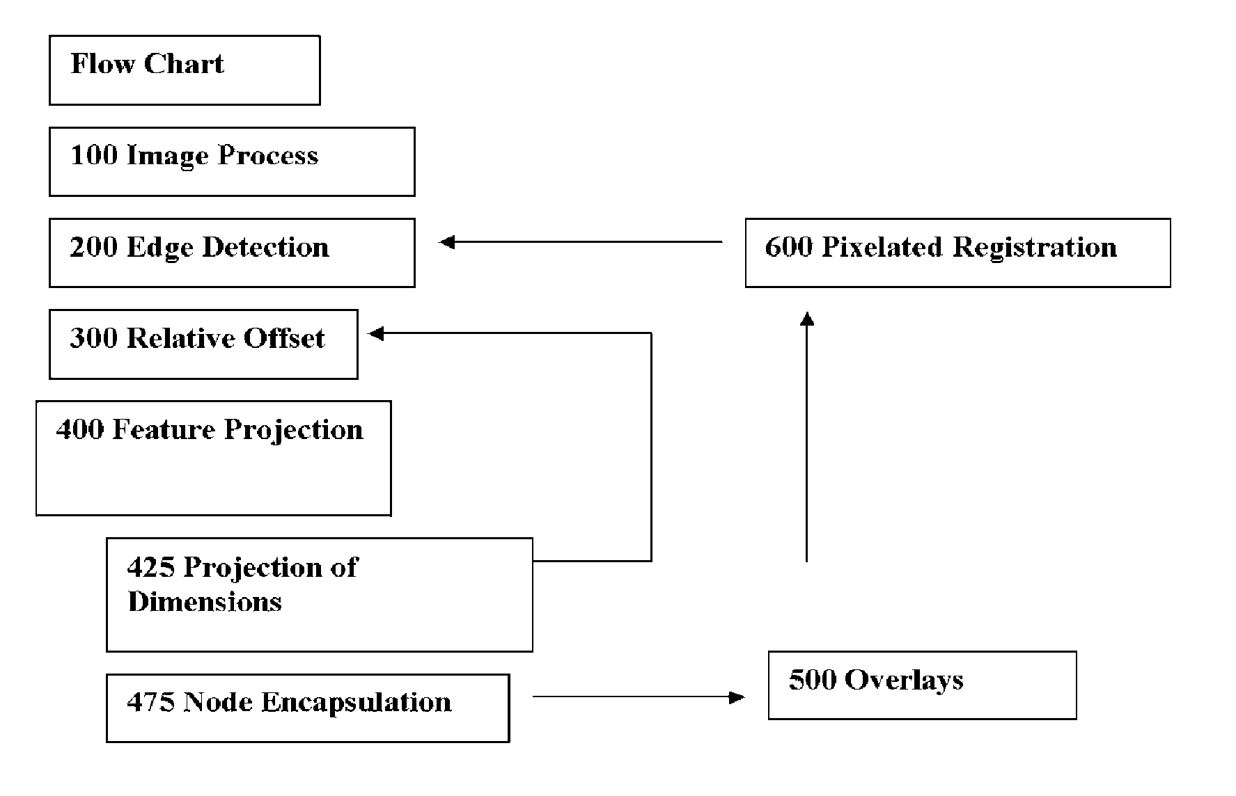
[0036] The method and apparatus in accordance with the present invention achieves image recognition wherein profound accuracy is achieved particularly in relation to any manual fabrication operation because measurements are made relative to existing features eliminating costly alignment processes. Aircraft components have magnitudes of features where relative overlays of digital images would further utilize the relative dimensioning of close up pictures providing high resolution from a plurality of vantage positions. The airbus example of the measurement of wet composite curvilinear components emphasize the ease of application of this technology by eliminating manual alignment required by traditional touch probe produces such as those offered by Starrett. Another example of fabrication deals with the necessity to get alignment in the form of square and cubic spaces. Custom sheet metal, HVAC, and kitchen cabinet installation would be greatly enhanced by facilitating the measurement o...


PUM


Abstract

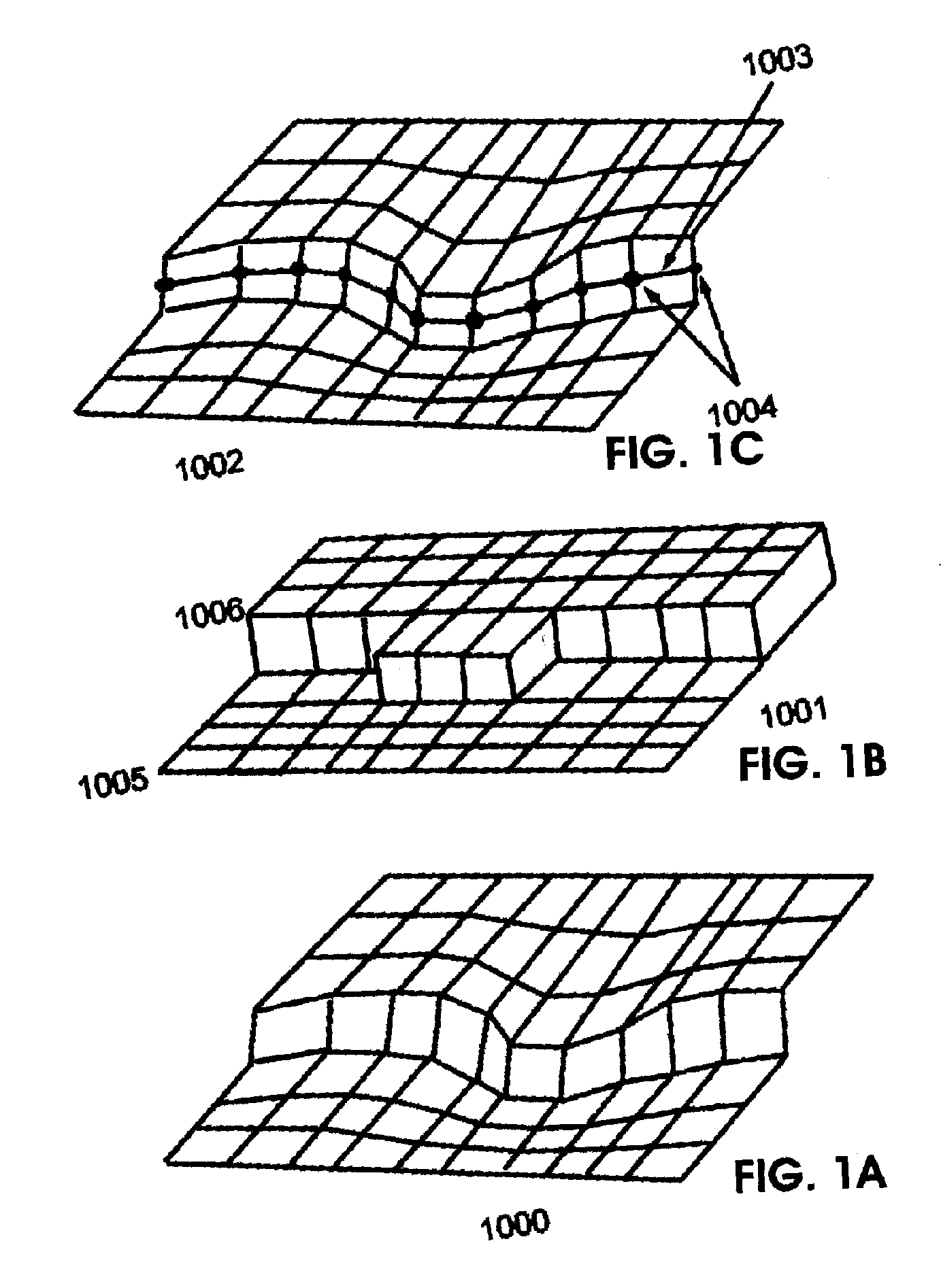
A method for image recognition of a material object that utilizes graphical modeling of the corner points of a vertex which includes projecting a point on a digital display to an inward depth, a one half pixel distance in the plane of the display, with a conic to a digital display, and a square block containing one half size child blocks that are scaled to depth, projecting the corner points of a vertex and replacing the bisecting points of edge features detected in a digital display scaled at an increasing rate of congruency to the dimensions of an object. The method may further include producing a digital image of the material object, providing a central processing unit, providing memory associated with a central processing unit; providing a display associated with a central processing unit; loading the digital image into the memory; defining the edges of features within the digital image; and a finding fight crucial points from registrations projected on to an edge feature display.

Description

RELATED APPLICATIONS [0001] This application is a continuation of provisional U.S. Patent application 60 / 604,880 filed on Aug. 28, 2004 Methods and apparatus for determining offsets of a part from a digital image.BACKGROUND OF THE INVENTION [0002] The invention relates to methods and apparatus for determining offsets of a part that are interchangeably described at the two possible projections of depth over a 45 degree oblique and offset the dimensions for projection within and including 45 degrees. The extended edge, comprised of triangulations, the plane of a primitive structure based on primitives of corner vertex elements share a local coordinate axis that has X, Y planar offsets projected in relation to a view plane or larger proportion blocks of features projected in the axis of the view normal. Similarly, the apparent offset within the limit of a 45 degree oblique is projected on the appropriate local axis corresponding to the edge feature triangulation plane. [0003] The inven...

Claims


Application Information

Patent Timeline
IPC IPC(8): G06K9/36
CPCG06T7/0006G06T2207/30164G06T7/0085G06T7/0028G06T7/33G06T7/13
Inventor HOLMES, DAVID
Owner HOLMES DAVID
Learn More