Implant for correction of pectus excavatum

a technology for pectus excavatum and implants, which is applied in the field of implants for correction of pectus excavatum, can solve the problems of deteriorating the growth or function of the organ positioned, prolonging and complicating the operation procedure, undue stress for both surgeons and patients, and achieves the effect of preventing pain and infection caused by stimulation of incised parts of the patient and facilitating the insertion of the chest correction bar

Inactive Publication Date: 2006-03-16
MEDIXALIGN
View PDF4 Cites 36 Cited by
  • Summary
  • Abstract
  • Description
  • Claims
  • Application Information

AI Technical Summary

Benefits of technology

[0012] The present invention provides an implant for correction of pectus excavatum in which a stabilizer is easily inserted into a chest correction bar. Once the stabilizer is inserted, pain and infection caused by stimulation to incised portions of a patient can be prevented.
[0016] Preferably, the fixing plates are centrally formed with through holes for reducing the weight of the stabilizer and for hitching threads as well in case of need.

Problems solved by technology

The disfiguring physical appearance of this deformity can cause emotional and social impact especially among children, and may give rise to deterioration in growth or function of organs positioned near the chest area, such that doctors recommend that the depressed chest be operated in childhood.
However, there are many disadvantages in the conventional surgical procedure thus described in that the costal cartilages should be carved out from inside the chest, the sternum should be lifted and portions of the grooves must be filled in, thereby prolonging and complicating the operation procedure.
It is also causes undue stress for both a surgeon and a patient who has to have his or her costal cartilages removed.
There is a disadvantage in the implant for correcting pectus excavatum thus described according to the prior art in that, because a planar surface of the fixation piece 22 at the stabilizer 20 is protrusively formed with the insertion piece 21, the overall thickness of the stabilizer 20 becomes larger, such that when the chest correction bar 10 is inserted, soft tissue around the operated portion are stimulated, causing pain to a patient, and in worst cases, soft tissue may become infected.

Method used


Image

  • Implant for correction of pectus excavatum
  • Implant for correction of pectus excavatum
  • Implant for correction of pectus excavatum

Examples


first embodiment

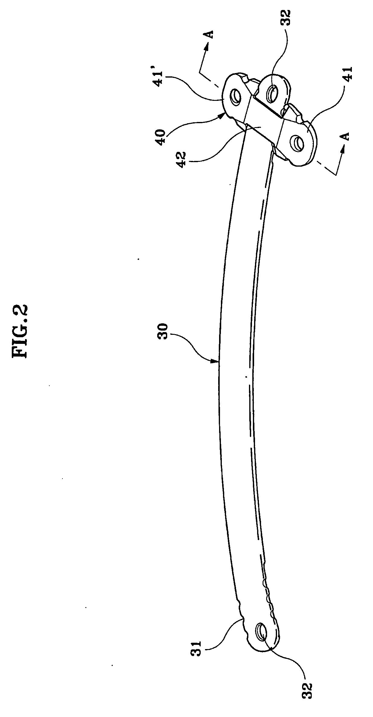
[0028]FIG. 2 is a coupled perspective view of an implant for correcting pectus excavatum according to the present invention and FIG. 3 is a partial cross-sectional view taken along A-A of FIG. 2.

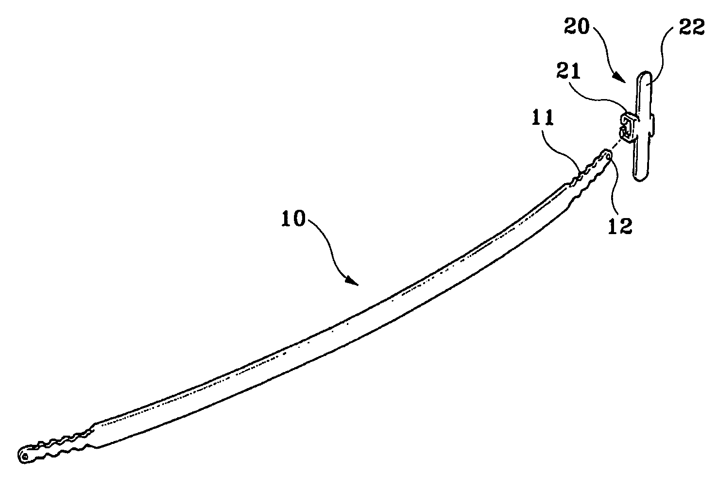
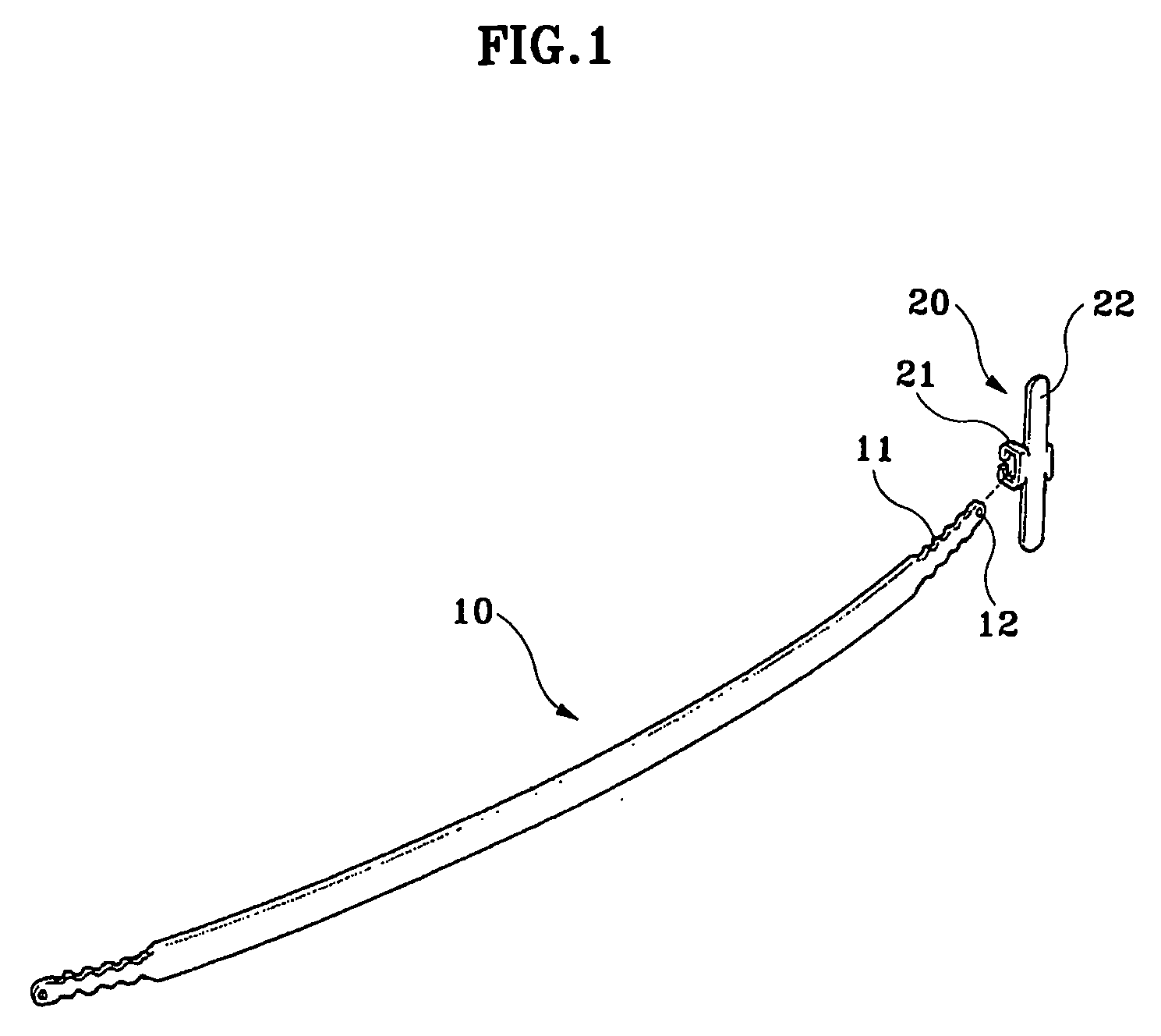
[0029] As depicted in the drawings, the implant according to the present invention comprises a chest correction bar 30 going through a body for lifting a depressed sternum and surrounding costal cartilages, and a stabilizer 40 for being inserted into a distal end of the chest correction bar 30 to prevent the chest correction bar 30 from being rotated inside the body.

[0030] The chest correction bar 30 and the stabilizer 40 are made of unharmful and rust-proof biocompatible metals such as stainless steel, titanium alloy, cobalt-chrome alloy and the like, and also may be made of biocompatible polymer or copolymer such as Utra High Molecular Weight Polythylene (UHMWPE), Poly L-Lactide Acid (PLLA), Poly Glycolic Acid (PGA), Poly D-Lactide Acid (PDLA).

[0031] As shown in FIGS. 2, 4a and 4b, the c...

second embodiment

[0039]FIG. 9 is a perspective view of a stabilizer of an implant according to the present invention.

[0040] The stabilizer 40 according to the teachings of the second preferred embodiment of the present invention is mounted with the protruders of the first embodiment in the form of pins 143 and 143′ attached to fixing plates 141 and 141′. The bridge 142, lateral grooves 141a and 141′a and through holes 141b and 141′b are the same as those of the first embodiment.

third embodiment

[0041]FIG. 10 is a perspective view of a chest correction bar of an implant according to the present invention.

[0042] An intermediate thickness assigned to a chest correction bar 230 according to the teachings of the third preferred embodiment of the present invention is thinner than distal ends of the chest correction bar such that a central portion of the chest correction bar 230 in between the two distal ends thereof is hollowed. Construction of lateral grooves 231, through holes 232 and recesses 233 are the same as that of the first embodiment of the present invention.

[0043] The chest correction bar 230 of the teachings of the third embodiment of the present invention therefore may be reduced in weight due to the hollowed central portion thereof to be stably coupled with a stabilizer.

[0044] The foregoing discussion has disclosed and described merely exemplary embodiments of the present invention. It is not intended to be exhaustive or to limit the invention to the precise form...


PUM


Abstract

An implant for correcting pectus excavatum is disclosed, which comprises a chest correction bar (30) inserted into a body for lifting a depressed sternum and costal cartilages, and a stabilizer (40) for being inserted into a distal end of the chest correction bar (30) to prevent the chest correction bar from being rotated inside the body, wherein the chest correction bar (30) is formed at both jagged distal ends thereof with recesses (33) each of a predetermined length along the lengthwise direction of the chest correction bar (30), and wherein the stabilizer (40) comprises: two fixing plates (41, 41′) for being fixed to the body of a patient; a bridge (42) connecting the two fixing plates (41, 41′); two protruders (43, 43′) each generally opposed from the fixing plates (41, 41′) so as to be hitched by the recesses (33) at the distal ends of the chest correction bar (30) inserted from under the bridge (42), where there are formed two spaces (C) each of a predetermined size between the two protuders (43, 43′) and two lateral lengthwise surfaces of the bridge (42) so that the distal ends of the chest correction bar (30) can be inserted thereinto, thereby allowing the stabilizer (40) to be easily inserted into the chest correction bar (30), and once the insertion is made, pain and infection caused by stimulation on incised portions of a patient can be prevented.

Description

FIELD OF THE INVENTION [0001] The present invention relates to an implant inserted into a body for correcting pectus excavatum. BACKGROUND OF THE INVENTION [0002] In general, chest deformity is a case where a chest is more depressed or bulged than that of a normal person due to a depression or elevation of a sternum and surrounding costal cartilages. A depressed chest (pectus excavatum), also known as funnel chest, is particularly the most common anterior chest wall deformity for Asian people. The disfiguring physical appearance of this deformity can cause emotional and social impact especially among children, and may give rise to deterioration in growth or function of organs positioned near the chest area, such that doctors recommend that the depressed chest be operated in childhood. [0003] One conventional surgical procedure for correcting pectus excavatum is to cut out a predetermined portion of inner costal cartilages positioned at both sides of a chest to form grooves therein. ...

Claims


Application Information

Patent Timeline
Patent Type & Authority Applications(United States)
IPC IPC(8): A61B17/56A61B17/80A61F2/30
CPCA61B17/8076A61F2/30
Inventor KIM, KYUNG-TAEKIM, JUNG-SUNGKIM, BYUNG-SOOSHIN, TAE-JINCHOI, YOUNG-HO
Owner MEDIXALIGN
Why Eureka
Try Eureka