
Fishing line casting and bait projectile system

a technology of projectiles and fishing lines, which is applied in the field of fishing line casting art, can solve the problems of imposing on the fisherman certain body postures, ineffective casting methods in confined quarters, and dangerous movements during casting

Active Publication Date: 2006-03-23
M DOOLEY PROD LLC
View PDF99 Cites 11 Cited by
  • Summary
  • Abstract
  • Description
  • Claims
  • Application Information

AI Technical Summary

Benefits of technology

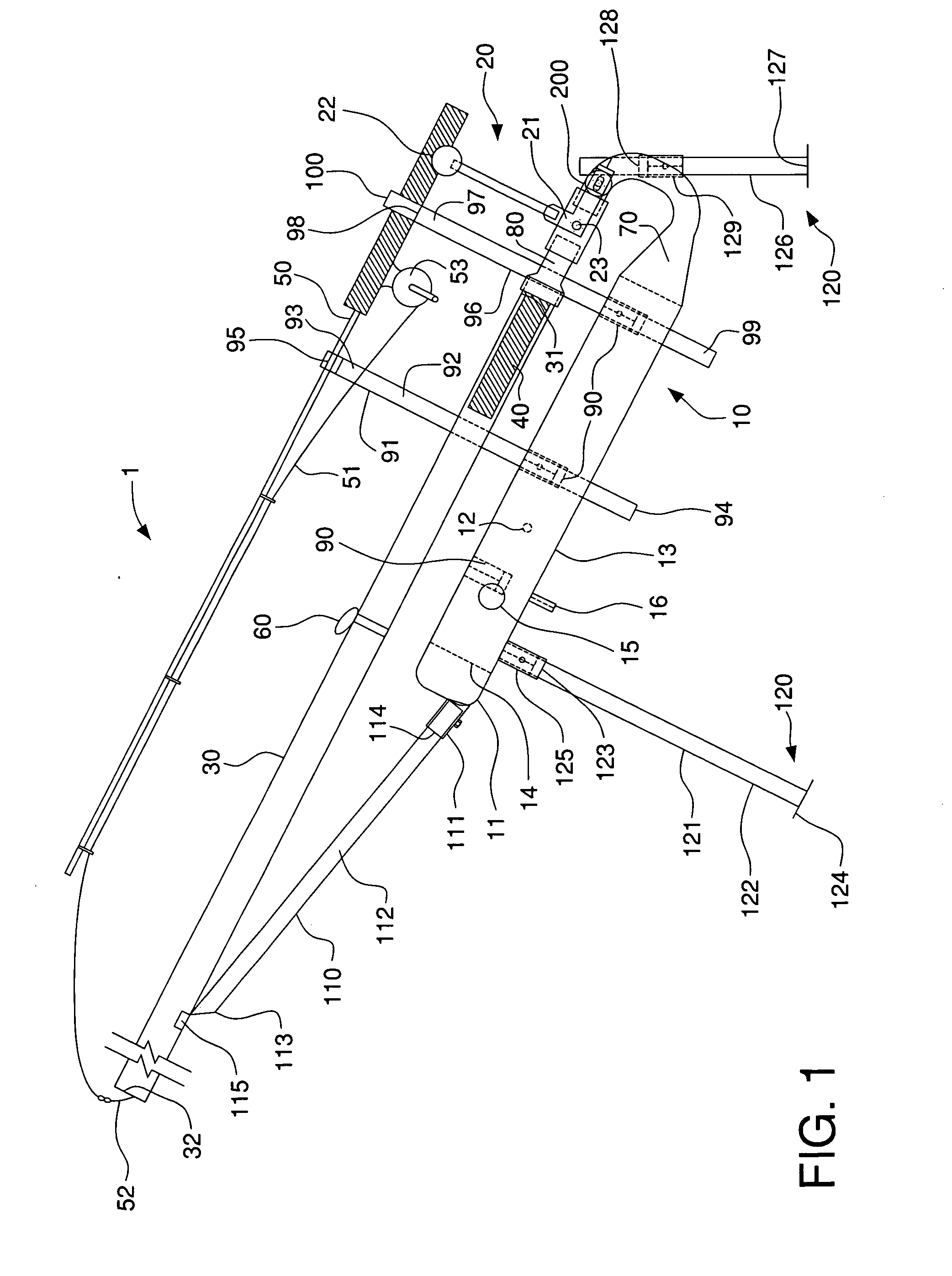
[0011] The present invention relates to a novel and improved fishing line casting system that is relatively simple in construction, which is easy to operate, and which provides accurate launching of a projectile and associated line to points at considerable remote distances. According to one embodiment of the invention, the projectile is a bait or lure and float or weight, to which a fishing line is coupled.
[0012] It is a general object of the instant invention to ease the task of casting bait or lures. Another object is to lessen the need for skill in casting, without sacrifice of distance or accuracy. A still further object is to enable casting in close quarters, as in a boat having a top.
[0015] It is a further object of the present invention to provide a launching system having a safety system such that when loaded, should the launching system be hit or fall violently, the safety system will prevent the launching of the projectile.

Problems solved by technology

The movement which is made during casting is very dangerous in that the sinker and fishhook describe a launch path from the rear of the fisherman's location and when launched may hit or hook objects or persons that are within the launch path.
Thus, most casting methods are ineffective in confined quarters and impose on the fisherman certain restrictive body postures.
This problem is exacerbated in the case of handicapped individuals whose strength and / or physical dexterity is compromised.
In general, these systems are complex, expensive, and generally impractical.
Consequently, such prior art devices have not proved to be completely satisfactory.
Moreover, in most instances when these devices are used the forward motion of the propellant rod section during the launching action is suddenly stopped when one mechanical portion physically strikes another with considerable force.
This tends to not only jerk the fishing rod from the operator's grasp but also strains certain parts of the rod each time it is used, thereby shortening the rod's useful life.
Such explosives are not only unsafe, but also expensive, and a user would be required to carry a considerable supply of the cartridges to launch the number of casts required of a typical fishing excursion.
Moreover, the spiked anchor member provides a single anchorage point for the device which is less than desirable with regard to device stability, safety and launching accuracy.
More particularly, explosive cartridges generate considerable force that may cause the device and the equipment carried thereby to suddenly shift if the spike is not firmly embedded in the ground.
In the event of such a shift, the user may be placed in danger, the projectile will miss its target and a blasting cap will be wasted.
Also, the orientation of the support cannot be adjusted without physically extracting the spiked end from the ground and forcing it back into the ground.
Such a procedure does not lend itself to precise position adjustments and may require considerable trial and error before a user achieves the desired projectile flight trajectory (which also may result in a number of wasted explosive charges if the support is incorrectly positioned).
Prior powered casting arrangements, therefore, have not met with wide-spread adoption and use as being too mechanically complicated, too expensive to manufacture, too restricted to specific types of terminal tackle, too unwieldy, and / or too functionally infeasible.

Method used


Image

  • Fishing line casting and bait projectile system
  • Fishing line casting and bait projectile system
  • Fishing line casting and bait projectile system

Examples


Embodiment Construction

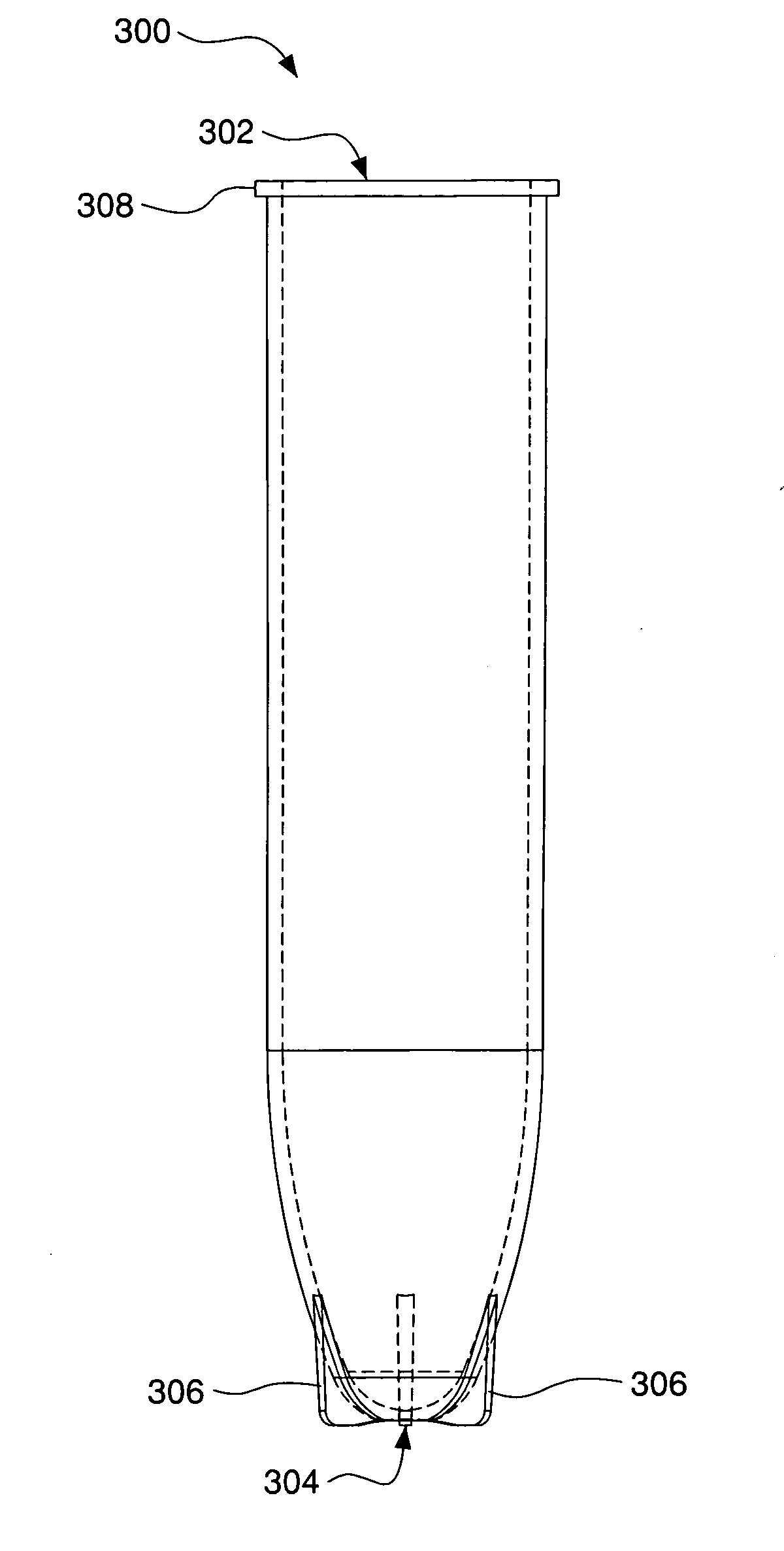
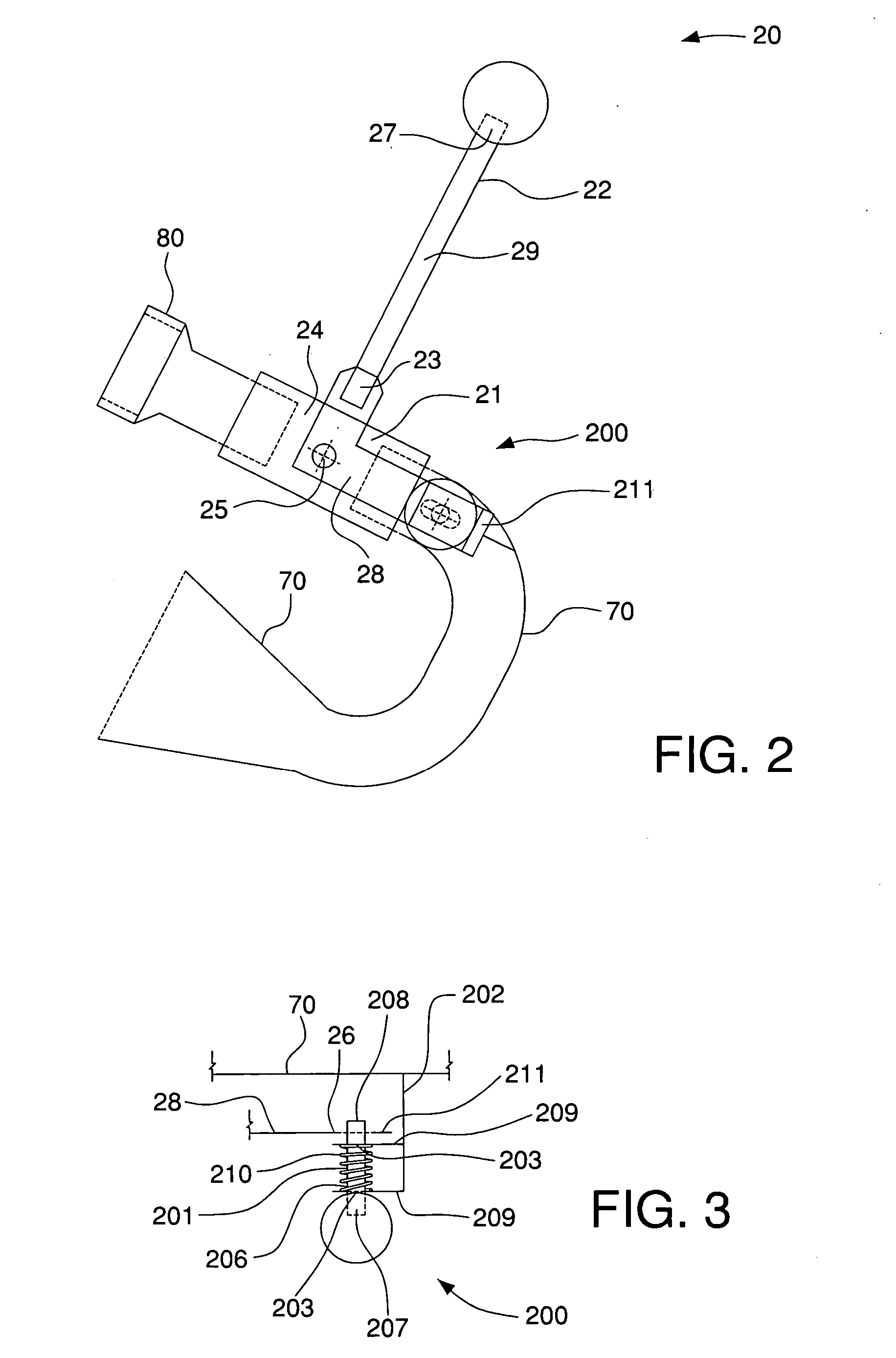
[0023]FIGS. 1-3 show one possible embodiment of a fishing line casting system 1 having features in accordance with the present invention. In a powered fishing line casting arrangement, the present invention contemplates not only the improved compressed gas fishing line casting arrangement in which conventional fishing rods, spinning reels, and other fishing tackle may be conveniently utilized without alteration, but also new and improved structures comprising the individual components of the system. New and improved control means 20 also may be utilized to control the flow of the compressed air. Additional embodiments are contemplated for use in a variety of environments. The apparatus may be utilized on a boat and the support means may vary upon stability requirements.

[0024] An integral part of the system is the projectile 40 that is launched by the fishing line casting system and to which the fishing line 51 and, if desired, the bait, is attached. New and improved projectiles als...


PUM

PropertyMeasurementUnit
lengthaaaaaaaaaa
lengthaaaaaaaaaa
depthaaaaaaaaaa

Abstract

A powered fishing line casting system utilizing compressed air is provided to cast a projectile provided with fishhooks and bait, and to which the fishing line to be cast is attached, to greater distances than could be achieved using conventional casting methods. The system includes a hollow launch tube sized to accommodate insertion of the projectile. A reducer is disposed adjacent to one end of the launch tube and is adapted to receive a flow of compressed gas from an accumulator tank and to discharge a stream of high-velocity air that impinges upon the projectile disposed within the launch tube in order to launch the projectile. A manually-operable valve is interposed between the reducer and the accumulator tank to control the flow of air to the reducer. Spaced-apart front and rear support legs provide stable support for the system during and between launches of a fishing line carrying projectile.

Description

CROSS REFERENCE TO RELATED APPLICATION [0001] The present application claims the benefit of U.S. Provisional Patent Application No. 60 / 611,861 filed Sep. 20, 2004, which is incorporated herein by reference in its entirety.FIELD OF THE INVENTION [0002] The present invention relates to the fishing line casting art and, more particularly, to an improved, compressed gas powered fishing line casting system for safely and reliably casting a projectile, to which the fishing line to be cast is attached, to a target area located a distance that could not be reached with conventional casting methods. BACKGROUND OF THE INVENTION [0003] The sport of fishing is practiced and enjoyed by a large percentage of the population. Many of those who engage in this sport practice that form of fishing known as casting. These fishermen cast from docks, from wharves, from boats, and into the surf, to state but a few examples. It is necessary in casting to have a sufficiently clear working area to facilitate ...

Claims


Application Information

Patent Timeline
Patent Type & Authority Applications(United States)
IPC IPC(8): A01K91/02
CPCA01K91/02
Inventor TRIANO, DANIELHEYER, THOMASOSENBAUCH, DOUGLAS
Owner M DOOLEY PROD LLC
Learn More