Air-fuel ratio control system and method

Inactive Publication Date: 2006-03-23
DENSO CORP
View PDF7 Cites 0 Cited by
  • Summary
  • Abstract
  • Description
  • Claims
  • Application Information

AI Technical Summary

Benefits of technology

[0007] The present invention addresses this drawback and has an object to efficiently purify exhaust emi

Problems solved by technology

If the amount of occluded oxygen in the downstream catalyst is large, on the other hand, the lean condition will not readily end even if the rich components flow from the upstream catalyst.
Therefore, a sufficient amount of rich components for ending the lean condition in the downstream catalyst cannot be supplied to the downstream catalyst.

Method used


Image

  • Air-fuel ratio control system and method
  • Air-fuel ratio control system and method
  • Air-fuel ratio control system and method

Examples


Embodiment Construction

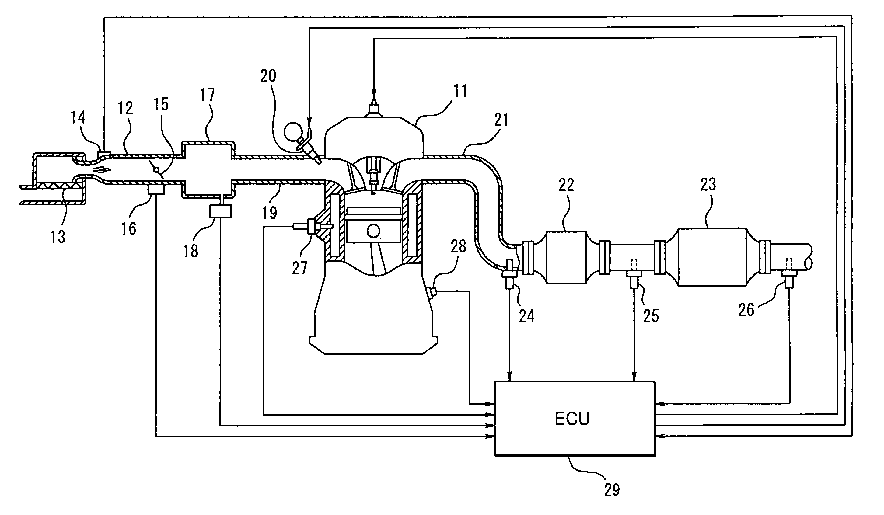
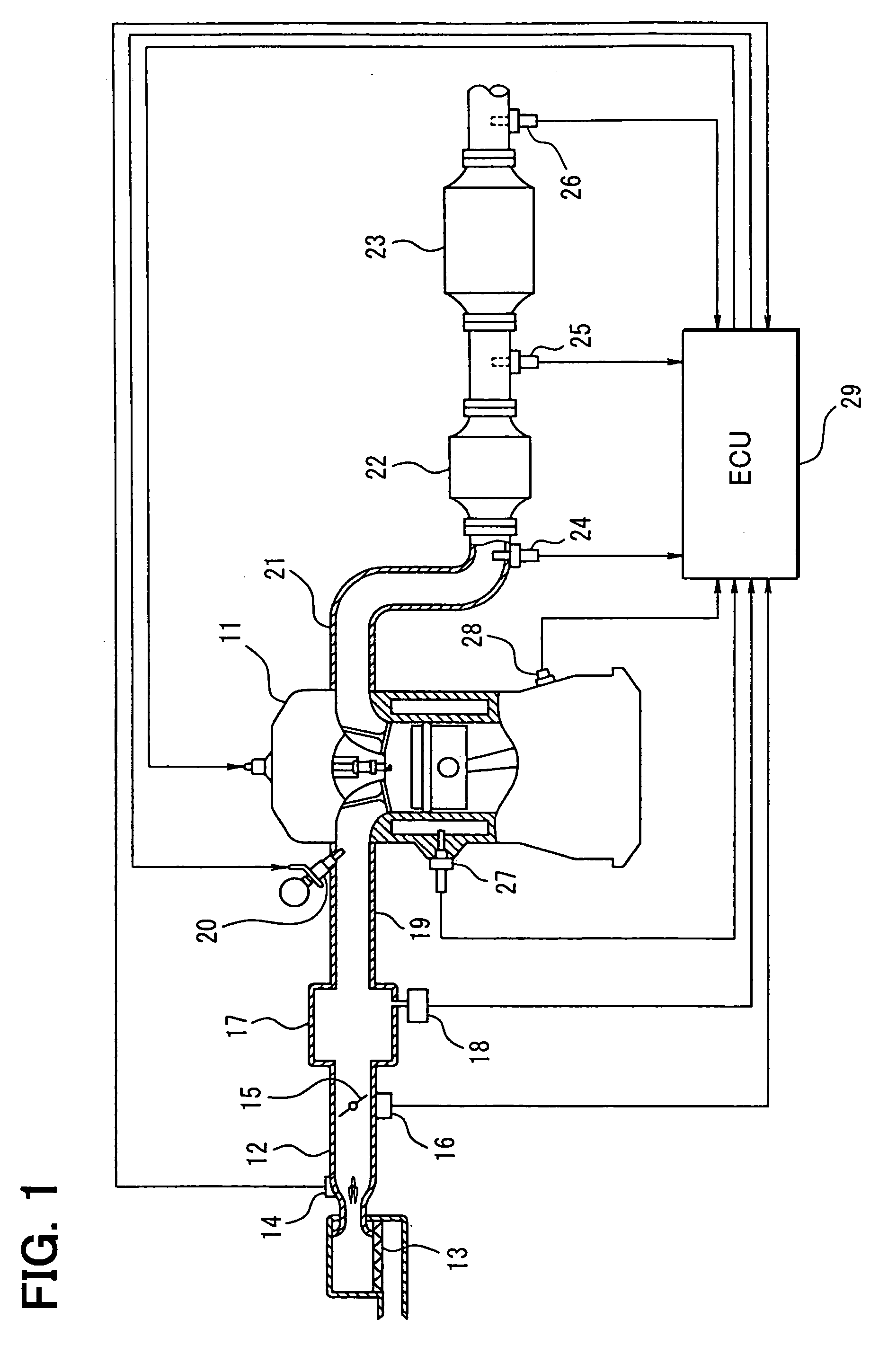
[0018] Referring first to FIG. 1, an internal combustion engine 11 is connected to an air cleaner 13 through an intake passage 12. An air flow meter 14 is provided downstream the air cleaner 13 to detect an intake air amount in the intake passage 12. A throttle valve 16 and a throttle sensor 16 for detecting a throttle position are provided downstream the air flow meter 16.

[0019] A surge tank 17 is provided downstream the throttle valve 15. A pressure sensor 18 is attached to the surge tank 17 for detecting an intake air pressure in the surge tank 17. Intake manifolds 19 of the engine 11 are connected to the surge tank 17. A fuel injector 20 is attached to each manifold 19 for injecting fuel near the intake port of the engine 11. A coolant temperature sensor 27 and a crank angle sensor 28 are attached to the engine 11 for detecting an engine coolant temperature and an engine rotation speed, respectively.

[0020] In an exhaust passage 21 of the engine 11, an upstream catalyst 22 and ...


PUM


Abstract

An air-fuel ratio control system has an upstream catalyst, a downstream catalyst, a first sensor for detecting a first air-fuel ratio present upstream the upstream catalyst, a second sensor for detecting a second air-fuel ratio present between the catalysts and a third sensor for detecting a third air-fuel ratio present downstream the downstream catalyst. An ECU determines a target second air-fuel ratio based on the detected third air-fuel ratio, and a target first air-fuel ratio based on the target second air-fuel ratio and the detected second air-fuel ratio. The ECU feedback controls an air-fuel ratio of mixture based on the target first air-fuel ratio and the detected first air-fuel ratio. The target first air-fuel ratio is corrected based on the detected third air-fuel ratio so that a change in the target first air-fuel ratio becomes smaller in a predetermined range other than a normal range.

Description

CROSS REFERENCE TO RELATED APPLICATION [0001] This application is based on and incorporates herein by reference Japanese patent application No. 2004-270867 filed on Sep. 17, 2004. FIELD OF THE INVENTION [0002] The present invention relates to an air-fuel ratio control system and method for internal combustion engines in which two catalysts are provided in series in an exhaust passage. BACKGROUND OF THE INVEHTION [0003] U.S. Pat. No. 6,539,707 (JP 2002-235584A) proposes an air-fuel ratio feedback control system. In this system, two catalysts, an upstream catalyst and a downstream catalyst, are provided in series in an exhaust passage of an internal combustion engine to purify exhaust emissions. A first exhaust sensor is provided upstream the upstream catalyst to detect a first air-fuel ratio there. A second exhaust sensor is provided intermediate the two catalysts to detect a second air-fuel ratio there. A third exhaust sensor is provided downstream the downstream catalyst to detect ...

Claims


Application Information

Patent Timeline
IPC IPC(8): F01N3/00
CPCF01N3/101F02D41/1441F01N13/009F01N13/0093Y02T10/22Y02T10/12
Inventor YAMASHITA, YUKIHIRO
Owner DENSO CORP
Why Eureka
Try Eureka