Steam trap with float

a technology of steam traps and traps, applied in the field of steam traps, can solve the problems of shortened life span of boilers and peripheral devices, large loss of energy such as gas, electricity, water, etc., and achieve the effects of simplifying the structure, avoiding mechanical problems, and facilitating the laying and repair of pipes

Inactive Publication Date: 2006-03-23
JOO SOON KYU +1
View PDF7 Cites 7 Cited by
  • Summary
  • Abstract
  • Description
  • Claims
  • Application Information

AI Technical Summary

Benefits of technology

[0010] Accordingly, the present invention has been made in view of the above-mentioned problems, and it is an object of the present invention is to provide a steam trap with a float having an inlet and an outl...

Problems solved by technology

The conventional steam trap having the bucket formed within the case periodically performs repetitive operations regardless of generation of condensate, and exhausts condensate contained therein only through the shaking of the bucket, resulting in much leakage of steam.
For example, in a laundry, the escape of steam from a chimney is caused due to problems associated with a conventional bucket-type steam trap.
In addition, a boiler should operate continuously due to the loss of steam caused in the conventional bucket-type steam trap at the time of setting steam pressure of the boiler, leading to a vast loss of energies such as gas, electricity, water, and so forth required for operating the boiler.
Moreover, the life span of ...

Method used


Image

  • Steam trap with float
  • Steam trap with float
  • Steam trap with float

Examples


Embodiment Construction

[0018] Reference will now be made in detail to the preferred embodiments of the present invention, examples of which are illustrated in the accompanying drawings.

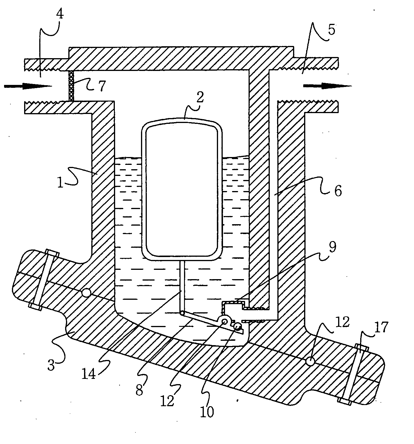
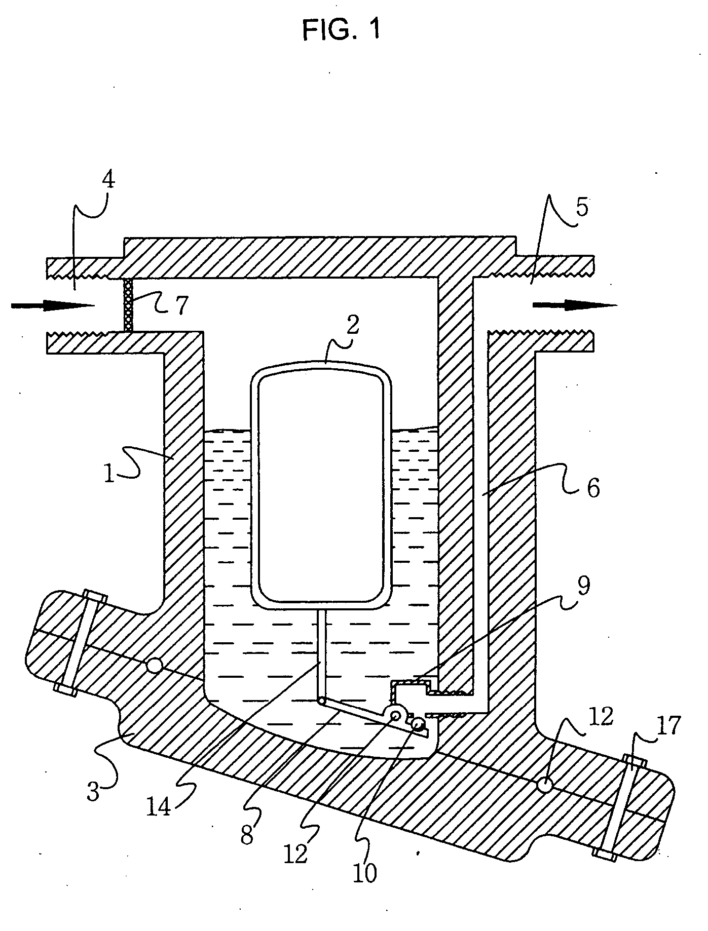
[0019]FIG. 1 illustrates a structure of a steam trap with a float according to an embodiment of the present invention. The steam trap includes a case 1 having an inlet 4 and an outlet 5 formed therein, a strainer 7, a float 2, an arm 14, a gate 9, a lever 8, and a valve plug 10. Condensate and steam flow in through the inlet 4 and flow out through the outlet 5. The strainer 7 is formed in the inlet 4. The float 2 is formed within the case 1. The arm 14 is formed at the bottom of the float 2. The gate 9 is screw-engaged with one side of the case 1 and has an orifice 11 formed therein. The lever 8 connects the gate 9 and the arm 14 to each other. The valve plug 10 is formed in the lever 8 to open / close the outlet 5.

[0020] The strainer 7 filters foreign substances of condensate flowing inside the case 1 and should be replace...


PUM


Abstract

Provided is a steam trap, in which an inlet and an outlet in a body are formed collinearily and a float for opening/closing the outlet is included. The steam trap having a float within a case includes the case, a cover, a strainer, the float, an arm, a gate, a lever, and a valve plug. The case includes therein an inlet through which condensate and water flow in and an outlet through which the condensate flow out. The cover is bolt-coupled to the case. The strainer is formed in the inlet and filters foreign substances. The float is formed within the case. The arm is formed at the bottom of the float. The gate is screw-engaged with one side of the case and has an orifice formed therein. The lever connects the gate and the arm. The valve plug is formed in the lever and opens and closes the outlet.

Description

BACKGROUND OF THE INVENTION [0001] 1. Field of the Invention [0002] The present invention relates to a steam trap, and more particularly, to a steam trap in which an inlet and an outlet are formed collinearly in a body and a float for opening / closing the outlet is mounted inside the body. [0003] 2. Background of the Related Art [0004] A steam trap, generally used in a heat exchanger, is a kind of automatic valve designed to efficiently remove condensate generated by condensation of steam in a drum or a pipe while preventing the leakage of live steam. [0005] U.S. Pat. Nos. 4,630,633 and 5,065,785 disclose steam traps. In these conventional steam traps, a bucket is formed to move by steam and condensate within a case and a vent is provided at one side of the top of the bucket. The bucket closes an outlet using the force of introduced steam, and the outlet is opened due to the weight of the bucket after steam escapes from the inside of the case through the vent. Through periodic repeti...

Claims


Application Information

Patent Timeline
IPC IPC(8): F16T1/20
CPCF16T1/24Y10T137/7439Y10T137/3068F16T1/26F16T1/38
Inventor JOO, SOON KYUJOO, SUN KYU
Owner JOO SOON KYU
Why Eureka
Try Eureka