
Trigger arrangement for a Marx generator

a technology of marx generator and trigger arrangement, which is applied in the direction of pulse train generator, pulse technique, instruments, etc., can solve the problems of high stress on the trigger electrode, complicated mechanical setup of the spark gap that can be triggered, etc., and achieves simple and inexpensive design, increased reliability, and reduced wear.

Active Publication Date: 2006-03-23
KERNFORSCHUNGSZENTRUM KARLSRUHE GMBH
View PDF8 Cites 4 Cited by
  • Summary
  • Abstract
  • Description
  • Claims
  • Application Information

AI Technical Summary

Benefits of technology

[0010] Possible embodiments for triggering the spark gap / s are described, which, on one hand, cause reliable triggering of the Marx generator and, on the other hand, permit an efficient setup.
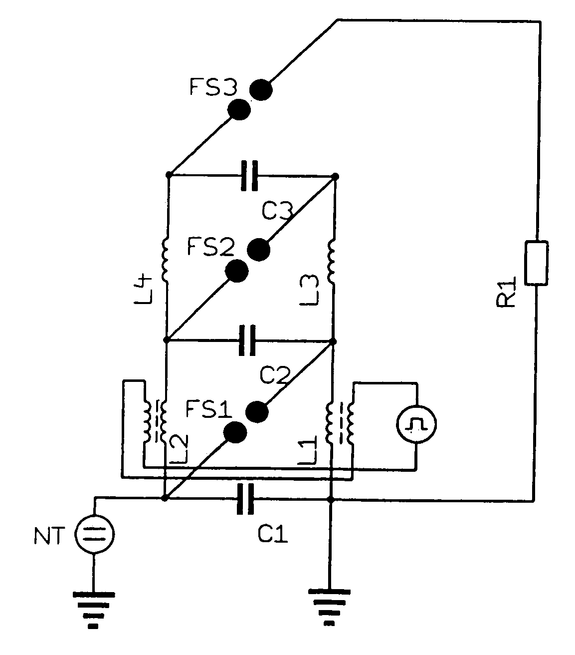
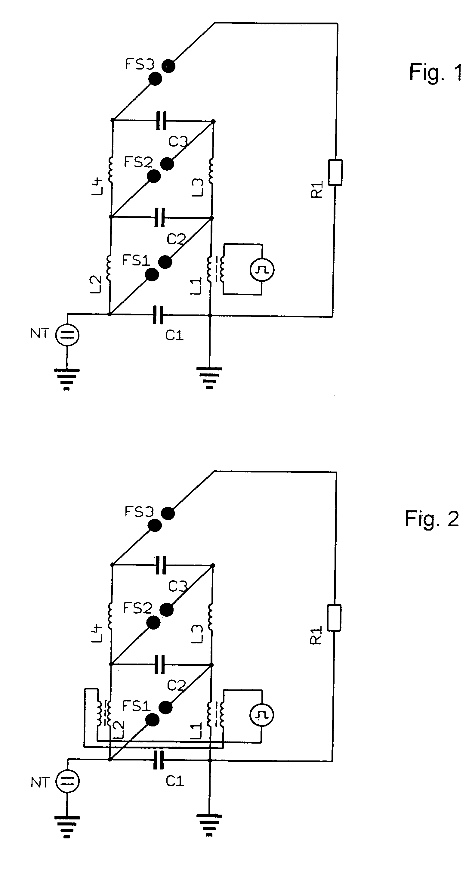
[0019] To increase the reliability, the winding direction of the input winding for the pulse transformer is such that the voltage induced in the input winding as a result of the increase of the discharge current of the Marx generator is oriented opposite to the voltage induced by the output winding in accordance with the principle of the transformer.
[0020] The advantages of the arrangement described in comparison with a conventional trigger method reside on one hand, in a simple inexpensive design and, on the other hand, in a substantially lower wear than in conventional three-electrode spark gaps. As a result, a Marx generator for an industrial application may be built which has a long-term constant operating behavior. For a reliable operation in industrial applications this is absolutely necessary.

Problems solved by technology

In spark gaps which can be triggered the trigger electrodes are subjected to high stress because of their exposed locations.
Furthermore, the mechanical setup of a spark gap that can be triggered is more complicated than a spark gap without a trigger electrode.

Method used


Image

  • Trigger arrangement for a Marx generator
  • Trigger arrangement for a Marx generator
  • Trigger arrangement for a Marx generator

Examples


Embodiment Construction

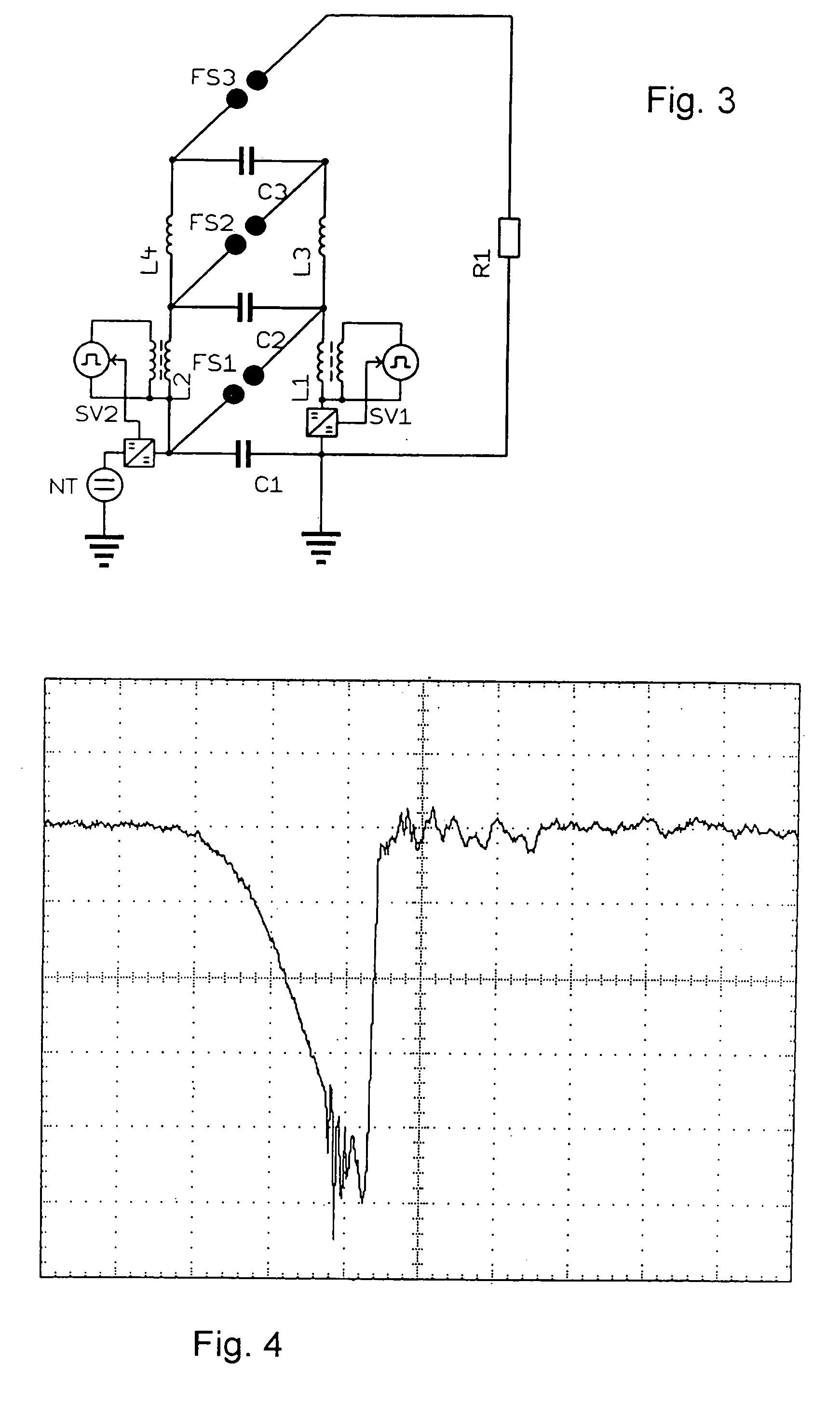
[0026] In the arrangement described below the breakdown of the first spark gap FS1 of the exemplary three-stage Marx-generator shown is obtained by the short application of an over-voltage. The Marx generator shown herein is designed for the repetitive operation and is therefore equipped with the charging coils L1 to L4, which switch the capacitors C1 to C3 in parallel for the charging process (see FIGS. 1 to 3). In this connection, for example, the grounded charging winding L1 also comprises the pulse transformer. The voltage generated by this transformer is added to the charge voltage of the capacitor of the first stage, and, with a suitable polarity, generates the excess voltage at the spark gap FS1 of this stage. The over-voltage consequently causes in a time-controlled manner the self-breakdown of the spark gap FS1.

[0027] As primary or input winding of the pulse transformer L1, a winding comprising only a few turns is used. With a primary pulse voltage of a suitable level whic...


PUM


Abstract

In trigger / firing arrangement in a Marx generator comprising n stage capacitors—n being a natural number greater than 1—, the same amount of spark gaps and 2(n−1) charging branches, with the spark gaps operating in a self-breakdown mode, the trigger- / firing arrangement comprises at least a pulse transformer connected to an pulse generator in at least one of the charging branches of the Marx-generator, which with the associated stage capacitor bridges a spark gap—except for the output end spark gap—a pulse transformer is disposed, whose output winding operates during charging as a charging winding and whose input winding is connected to the pulse generator in such a way that the voltage pulse generated with this pulse transformer during triggering of the pulse generator is added to the charge voltage of the associated stage capacitor and, with a corresponding polarity, generates an over-voltage sufficient for initiating self-breakdown at this spark gap.

Description

[0001] This is a continuation-in-part application of international application PCT / EP2004 / 004101 filed Apr. 17, 2004 and claiming the priority of German application 103 20 435.3 filed May 8, 2003. BACKGROUND OF THE INVENTION [0002] The invention relates to a trigger / firing arrangement of a Marx generator including n stage capacitors n being a natural-number greater than 1—the same amount of switches / spark gaps and 2(n−1) charging branches with the spark gaps operating in a self-breakdown mode. [0003] With a uni-polar output voltage, the Marx generator has generally as many spark gaps as it has stage capacitors. In its most simple construction, the spark gaps operate in self-breakdown mode. To each spark gap, except for the output spark gap, two charging branches are connected, one to each of the two connectors of the spark gap. As a result, there are altogether 2(n−1) charging branches associated with an n-stage Marx generator. With a charging voltage U at each of the stage capacito...

Claims


Application Information

Patent Timeline
IPC IPC(8): F23Q5/00H03K3/537
CPCH03K3/537
Inventor SACK, MARTIN
Owner KERNFORSCHUNGSZENTRUM KARLSRUHE GMBH
Learn More