Apparatus, method and program for verification of transmission margin

a transmission margin and apparatus technology, applied in the field of automatic verification of transmission margins, can solve the problems of one-channel delay in the generation of interrupt signals, one-channel time loss, and failure to constitute grounds to ensure product performance, so as to reduce the number of verification process steps and simplify the verification process

Inactive Publication Date: 2006-03-23
FUJITSU LTD
View PDF2 Cites 9 Cited by
  • Summary
  • Abstract
  • Description
  • Claims
  • Application Information

AI Technical Summary

Benefits of technology

[0024] (2) Simplifies the verification process or reduces the number of verification process steps and establishes the automatic verification of the transmission margin covering various items

Problems solved by technology

While the transmission margin verification in a transmission line has been conducted through theoretical calculations based on the specification of each of the components in the transmission line and the general transmission engineering theories, the verification results thereof have fallen short of constituting grounds to guarantee the product performance because of many errors.
Japanese Patent Application Laid-Open Publication No. 1993-276039 does little more than disclose an anti-malfunction A / D conversion apparatus with a shorter conversion time to solve the problem that if the A / D conversion starts with an external trigger from an external trigger input terminal that is also used as an analog input terminal, those signals input as external trigger signals rather than as analog signals are also subjected to an A / D conversion, that this conversion creates a one-channel time loss until the A / D conversion is complete, and that this gives rise to a one-channel delay in the generation of an interrupt signal.
Incidentally, a transmission margin of a transmission line is unacceptable as grounds to guarantee the product performance if the verification of the margin is not appropriate.

Method used


Image

  • Apparatus, method and program for verification of transmission margin
  • Apparatus, method and program for verification of transmission margin
  • Apparatus, method and program for verification of transmission margin

Examples


first embodiment

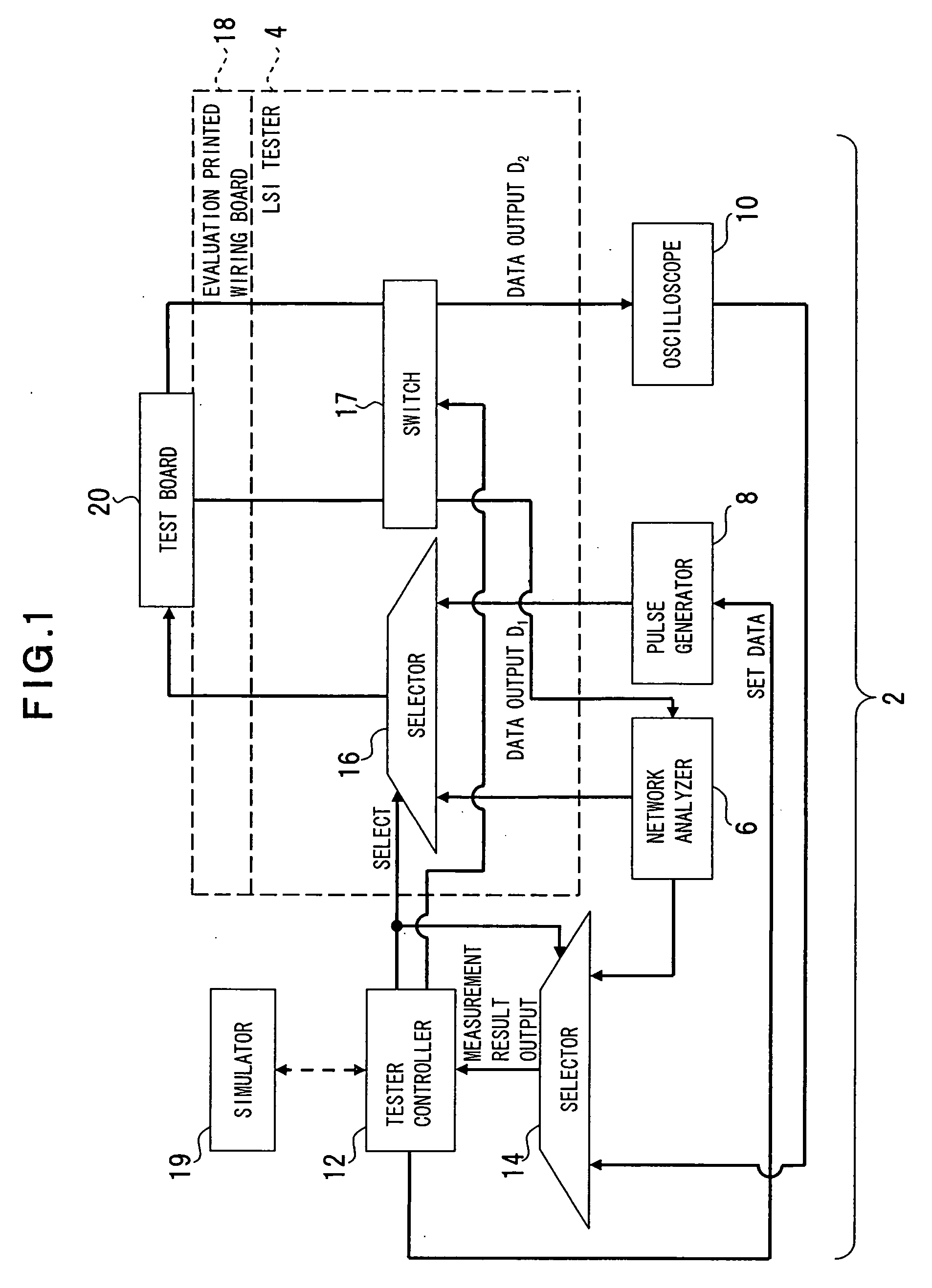
[0053] A first embodiment of the present invention will be described with reference to FIG. 1. FIG. 1 shows a transmission margin verification apparatus according to this embodiment.

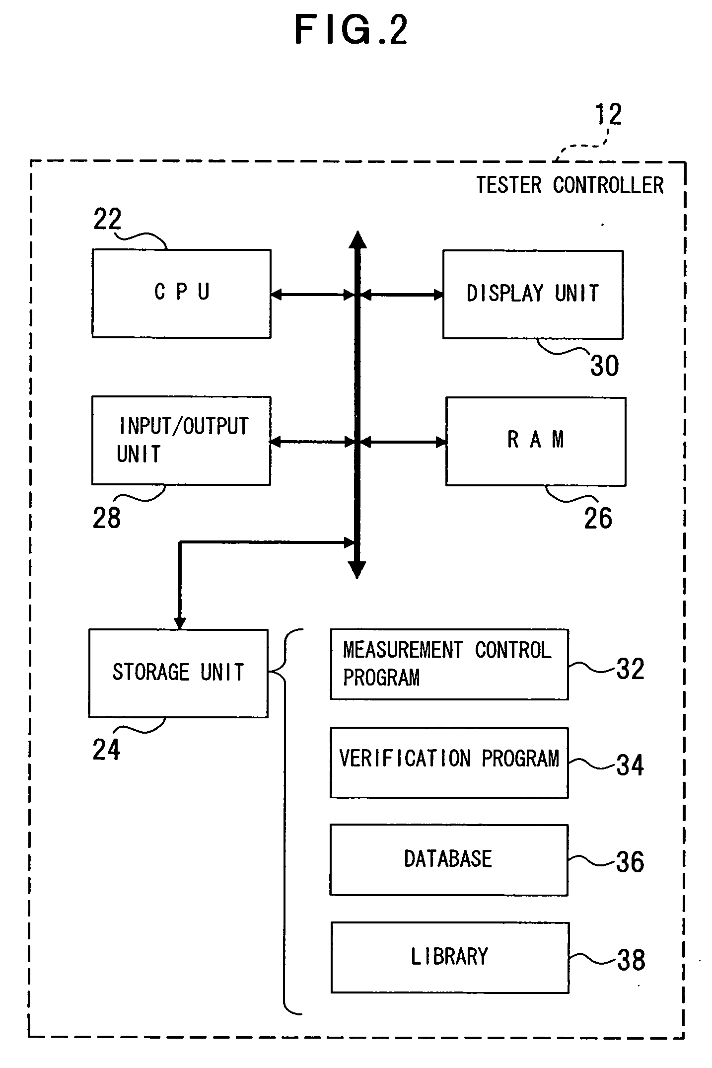
[0054] A transmission margin verification apparatus 2 is provided with an LSI (Large Scale Integration) tester 4, a network analyzer 6, a pulse generator 8, an oscilloscope 10 and the like as a plurality of measuring devices as an example of a measurement unit and also provided with a tester controller 12. In this embodiment, the network analyzer 6, the pulse generator 8 and the oscilloscope 10 are used in combination with the LSI tester 4 as a plurality of individual measuring devices. On the other hand, the tester controller 12 is an example of a function control unit of various measuring devices as with a measurement data arithmetic processing unit. That is, the tester controller 12 selects and / or controls the functions of each of the measuring devices to implement the automatic measurement / verificat...

second embodiment

[0086] Description will be given next of the transmission margin verification method and verification program thereof according to a second embodiment with reference to FIGS. 15 and 16. FIG. 15 shows an outline of the target device whose transmission margin is to be calculated, whereas FIG. 16 shows the transmission margin calculation steps. The same reference numerals are used for the same components as those in FIGS. 5 and 6.

[0087] To simplify the description in this embodiment, the simplified target device 44 is used, for example, as shown in FIG. 15. This target device 44 is provided with the PT boards 46, 48 and 50 that are connected to each other with the connectors 58 and 60. Transmitting devices 52A and 52B are provided on the PT board 46, whereas receiving devices 54A and 54B are provided on the PT board 48. A transmission line 66A, i.e., a target transmission system, mediates between the transmitting device 52A and the receiving device 54A, whereas a transmission line 66B...

third embodiment

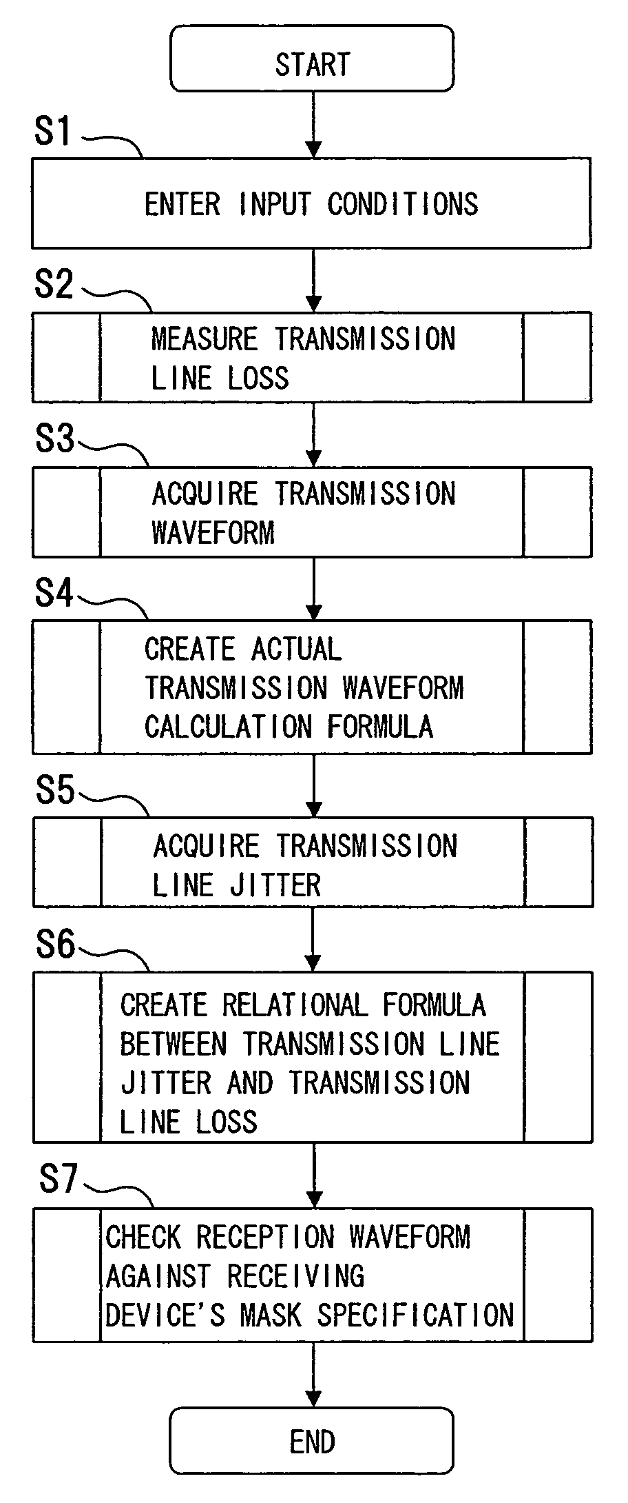
[0120] Description will be given next of the transmission margin verification apparatus, verification method and verification program thereof according to a third embodiment of the present invention with reference to FIGS. 23 to 27. FIG. 23 shows an example of the process steps of the transmission margin verification method and verification program thereof according to this embodiment. FIG. 24 shows a waveform acquired to verify the transmission margin. FIG. 25 shows an eye pattern formed from the acquired waveform. FIG. 26 shows the calculation of the waveform margin. FIG. 27 shows the transmission margin.

[0121] To calculate the transmission margin in this embodiment, as shown in FIG. 23, a waveform is acquired (step S41) first, followed by the creation of an eye pattern (step S42), the creation of an inner plot of the eye pattern (step S43) and the calculation of the transmission margin (step S44).

[0122] In the acquisition of a waveform (step S41), a signal pattern having succes...


PUM


Abstract

The present invention relates to verification of a transmission margin of various transmission lines transmitting a signal such as a high-speed digital signal and ensures improved verification accuracy. A transmission margin verification apparatus according to the present invention is configured with a measurement unit (e.g., LSI tester 4, network analyzer 6, pulse generator 8, oscilloscope 10) operable to measure a transmission loss and a leading edge waveform of pseudo transmission lines (e.g., transmission lines 56, 62, 66) corresponding to a target device 44 to be verified, and a calculation unit (tester controller 12) operable to reference the transmission line loss and the leading edge waveform measured by the measurement unit, calculate a transmission waveform of the target device, and associate the transmission waveform with a mask of the target device to calculate a transmission margin of the target device.

Description

BACKGROUND OF THE INVENTION [0001] 1. Field of the Invention [0002] The present invention relates generally to automatic verification of transmission margins of various types of transmission lines transmitting signals such as high-speed digital signals, and more particularly, to a transmission margin verification apparatus, method and program using a combination of existing measuring devices to effect the automatic verification. [0003] 2. Description of the Related Art [0004] The transmission speed of a digital signal in digital electronic equipment is becoming faster in recent years against the backdrop of the increased amount of information processed that is demanded of such equipment. This is the reason why the verification of a transmission margin is required in transmission lines transmitting high-speed digital signals. [0005] While the transmission margin verification in a transmission line has been conducted through theoretical calculations based on the specification of each ...

Claims


Application Information

Patent Timeline
Patent Type & Authority Applications(United States)
IPC IPC(8): H04L12/56G01R29/02
CPCH04L49/90H04L49/9023
Inventor TSUBAMOTO, DAITA
Owner FUJITSU LTD
Why Eureka
Try Eureka