Optimized high throughput analytical systems

a high throughput, analytical technology, applied in the direction of analytical using chemical indicators, laboratory glassware, instruments, etc., can solve the problems of small pressure gradient along the microchannel, severe decrease in throughput efficiency, and plugging of fluid material in the microfluidic elements, so as to reduce the dispersion rate and/or average velocity of fluidic material.

Inactive Publication Date: 2006-03-23
CAPLIPER LIFE SCI INC
View PDF20 Cites 140 Cited by
  • Summary
  • Abstract
  • Description
  • Claims
  • Application Information

AI Technical Summary

Benefits of technology

[0008] In one aspect, the invention comprises an integrated system or microfluidic device having a body structure with at least one microchannel with a cross-sectional geometry configured to manipulate a dispersion rate and/or an average velocity of at least one fluidic material. Such integrated system or microfluidic device further has one or more detection regions of the microchannel; a source(s) of one or more fluidic materials coupled to the microchannel; fluid direction systems and a detection system proximal to the detection region. Such microchannel in the system or device optionally has a cross-sectional geometry that manipulates the dispersion rate and/or the average velocity of the fluidic material relative to the dispersion rate and/or average velocity of the same fluidic material in a microchannel having a substantially rectangular cross-sectional geometry. In some embodiments, at least 2 fluidic materials each having a dispersion rate and/or each having an average velocity are flowed through the system/device. The cross-sectional geometry of the microchannel optionally manipulates the dispersion rates and/or average velocities of such fluidic materials to either be the same and/or to be different rates/velocities (e.g., 1.25, 1.5, 1.75, 2, 3, 4, 5, or 10 times different, i.e., the dispersion rate and/or average velocity of one fluidic material is 1.25, etc. times greater than the other).
[0009] In other aspects, the invention comprises a method of manipulating a dispersion rate and/or average velocity of a fluidic material in an integrated system or microfluidic device by flowing the material through a microchannel whose cross-sectional geometry is configured to manipulate the dispersion rate and/or average velocity relative to the dispersion rate and/or average velocity of the same fluidic material in a microchannel of substantially rectangular cross-sectional geometry. In some embodiments, such method includes flowing at least 2 fluidic materials through the microchannel, each material having a dispersion rate and/or average velocity. The cross-sectional geometry of the microchannel is optionally specifically configured to manipulate the dispersion rates and/or average velocities of the fluidic materials to either be the same and/or to be different rates/velocities (e.g., one rate/velocity being 1.25, 1.5, 1.75, 2, 3, 4, 5, or 10 times greater than the other rate/velocity). In some embodiments, the microchannels of such systems/devices change over the length of the microchannels. Also such systems/devices optionally comprise fluid direction systems using one or more of electrokinetic flow, positive pressure, negative pressure, hydrostatic pressure, or wicking forces (or a combination of such) as well as optionally comprising an operably attached computer attached to the detection system for acquiring data and tracking dispersion rates and/or average velocities of the fluidic materials.
[0010] In other aspects, the invention comprises a microchannel with one or more region whose cross-sectional geometry is configured to manipulate the dispersion rate and/or average velocity of at least one fluidic material relative to the dispersion rate and/or average velocity of the same material in a microchannel of substantially rectangular cross-sectional geometry. Such manipulation can be to increase and/or to decrease the dispersion rate and/or average velocity of the fluidic material. In some embodiments, multiple fluidic materials are flowed through the microchannel (e.g., a first fluidic material and at least a second fluidic material) each of which has a dispersion rate and/or average velocity (e.g., a first dispersion rate and/or average velocity and a second dispersion rate and/or average velocity, etc...

Problems solved by technology

This is especially true in high throughput systems where muddying or intermingling of sample plugs can severely decrease throughput efficiency.
However, various flow regimens used in microfluidic devices can lead to dispersion of plugs of fluid material in the microfluidic elements (e.g.,...

Method used


Image

  • Optimized high throughput analytical systems
  • Optimized high throughput analytical systems
  • Optimized high throughput analytical systems

Examples


example integrated

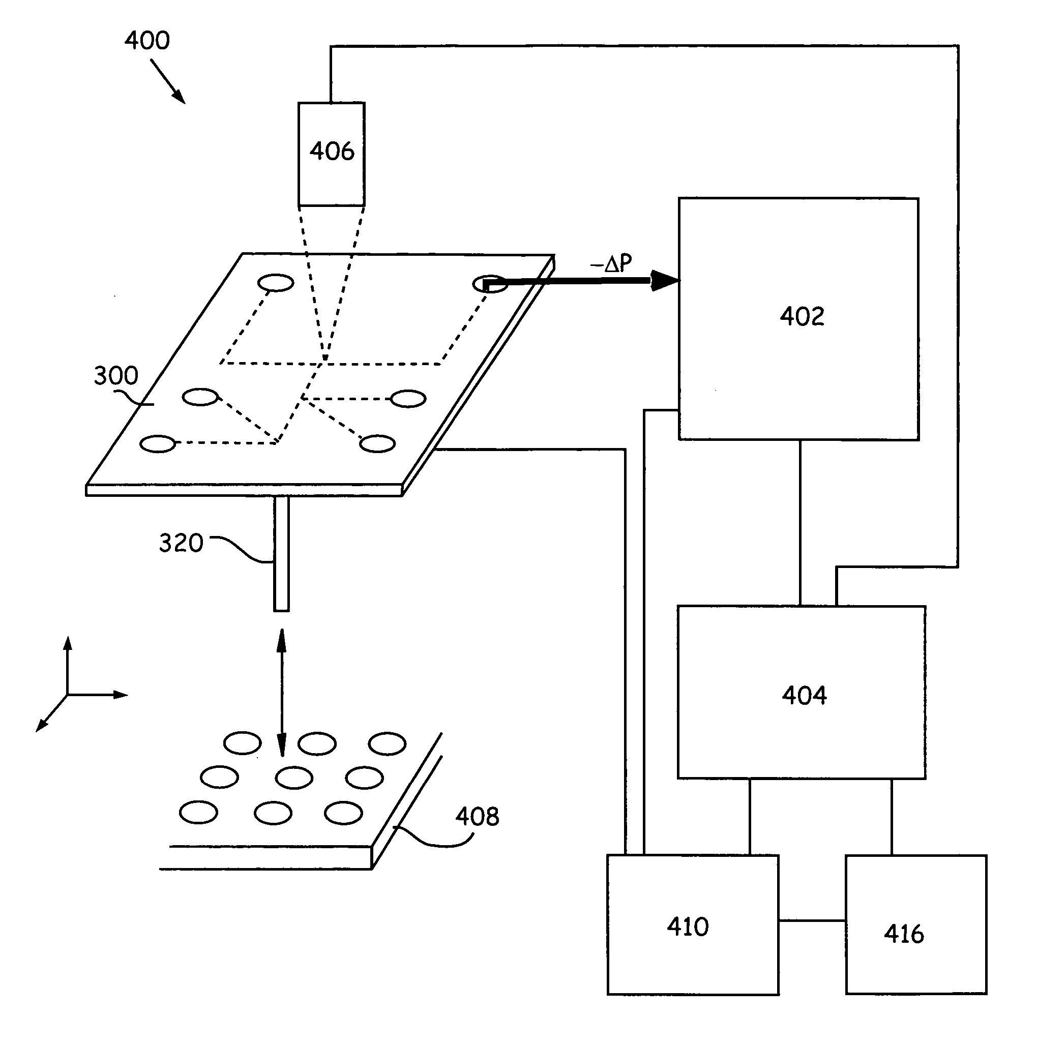
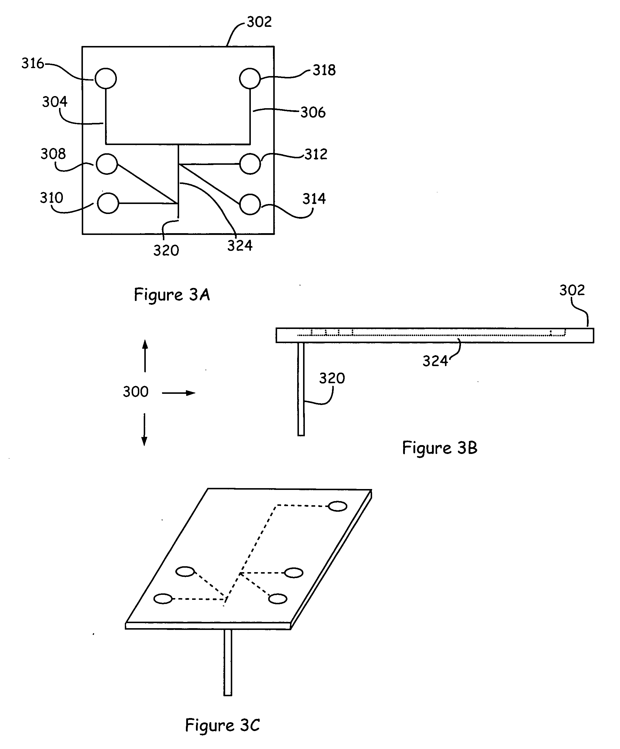
[0137] Example Integrated System

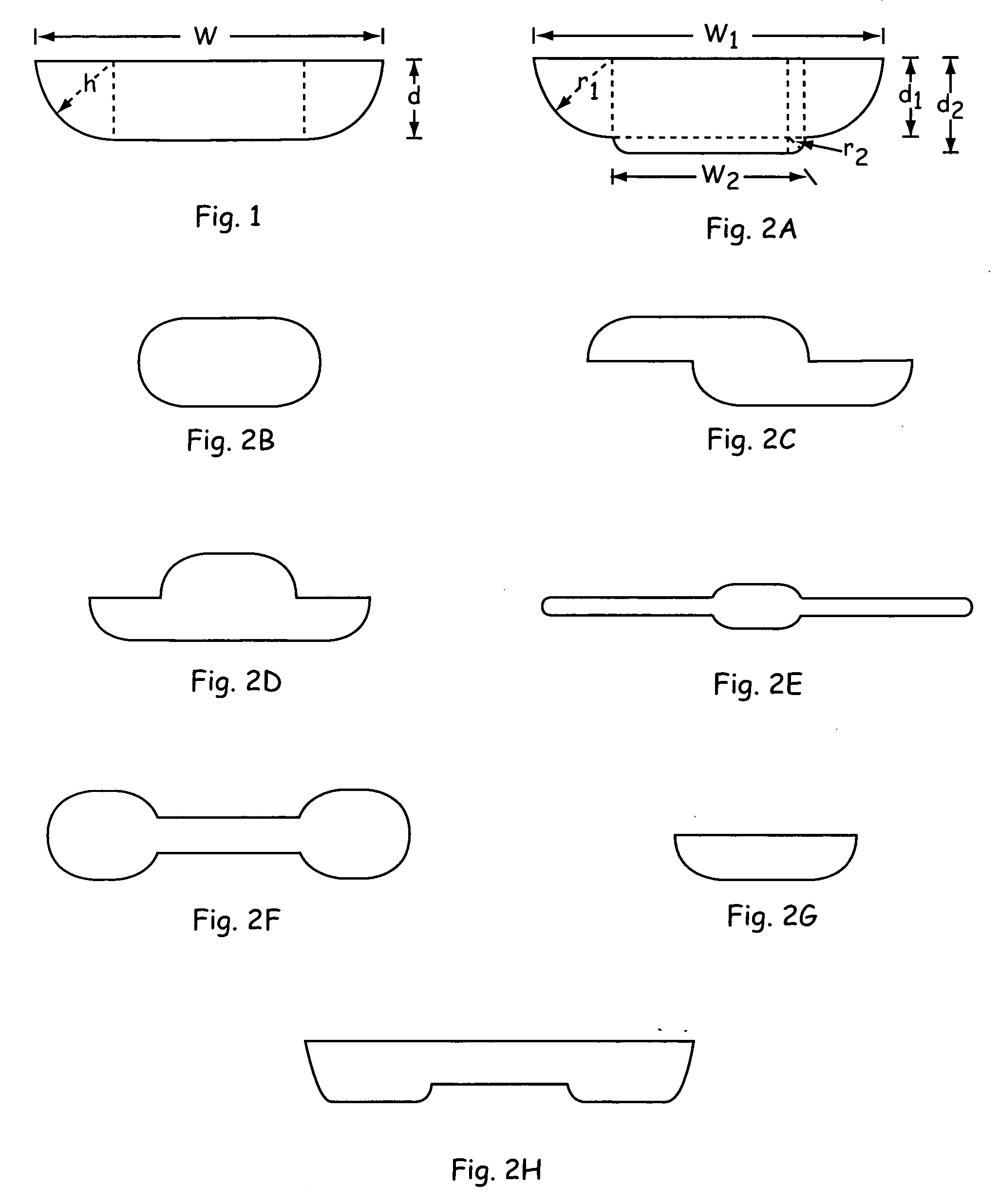
[0138]FIG. 3, Panels A, B, and C and FIG. 4 provide additional details regarding example integrated systems that optionally use the devices of the invention and optionally are used to practice the methods herein. As shown, body structure 302 has main channels 304 and 306 disposed therein. As stated previously, microchannels can comprise a number of areas comprising specifically configured cross-sectional geometry used to manipulate dispersion rates and / or average velocity (e.g., 304) additionally, numerous microchannels can comprise channels of “regular” cross-sectional geometry wherein fluidic materials are separated based on their differing dispersion rates and / or average velocity using non-electrokinetic flow (e.g., 306).

[0139] A sample or mixture of components, e.g., typically a buffer, sample, reagent, etc., is optionally flowed from pipettor channel 320 towards, e.g., reservoir 316, e.g., by applying a vacuum at reservoir 316 (or another point ...


PUM

PropertyMeasurementUnit
Forceaaaaaaaaaa
Pressureaaaaaaaaaa
Dispersion potentialaaaaaaaaaa

Abstract

The present invention provides novel microfluidic devices and methods for controlling/manipulating fluidic materials in microfluidic devices. In particular, the devices and methods of the invention create and utilize differences between dispersion rates and/or average velocity of fluidic materials in order to manipulate fluidic materials.

Description

CROSS-REFERENCE TO RELATED APPLICATIONS [0001] This application is a continuation of U.S. patent application Ser. No. 10 / 206,787, filed Jul. 26, 2002, which claims the benefit of U.S. Provisional Patent Application No. 60 / 308,368, filed Jul. 27, 2001, both of which are incorporated herein by reference in their entirety for all purposes.BACKGROUND OF THE INVENTION [0002] When carrying out chemical or biochemical analyses, assays, syntheses or preparations, a large number of separate manipulations are performed on the material(s) or component(s) to be assayed, including measuring, aliquotting, transferring, diluting, mixing, separating, detecting, incubating, etc. Microfluidic technology miniaturizes these manipulations and integrates them so that they can be executed within one or a few microfluidic devices. For example, pioneering microfluidic methods of performing biological assays in microfluidic systems have been developed, such as those described by Parce et al., “High Throughpu...

Claims


Application Information

Patent Timeline
IPC IPC(8): B01L3/00B01F23/00
CPCB01L3/502707B01L3/502746B01L2300/0816B01L2300/0858B01L2300/0877Y10T436/2575B01L2400/0487B01L2400/084G01N27/44743Y10T436/25B01L2400/0406
Inventor CHOW, ANDREA W.WADA, H. GARRETT
Owner CAPLIPER LIFE SCI INC
Why Eureka
Try Eureka