Fitting for a liquid-tight cable leadthrough

a technology of liquid-tight cable and leadthrough, which is applied in the direction of cable inlet sealing means, contact members penetrating/cutting insulation/cable strands, multi-purpose tools, etc., to achieve the effect of uniform transmission of force, simple installation and reduced thickness

Active Publication Date: 2006-03-23
AIRBUS OPERATIONS GMBH
View PDF15 Cites 33 Cited by
  • Summary
  • Abstract
  • Description
  • Claims
  • Application Information

AI Technical Summary

Benefits of technology

[0011] According to an exemplary embodiment a cable leadthrough that fulfills the initially described requirements may be realized with a fitting according to the invention for liquid-tight cable leadthroughs in solid surfaces, which solid surfaces can be gripped from the back (“hintergreifbare feste Fläche”). The fitting according to this exemplary embodiment may comprisea moulded element (“Formkörper”) of an elastic material that at least almost completely fills out the opening in the solid surface provided for installing the respective cable, for example, a bore in the floor of an on-board kitchen. Openings for accommodating the cables may lead through the elastic moulded part. The elastic moulded part may have a cross section that approximately corresponds to the shape of the opening for installing the cable leadthrough. A particularly simple installation may be achieved if the cross section of the elastic moulded part is chosen such that a slight clearance for the installation of the cable leadthrough remains between the part of the moulded element situated in the opening and the wall of the opening. On its front faces, the elastic mounded element may be bordered by two solid plates. An upper end plate may completely cover the opening for the installation of the cable leadthrough and may have such dimensions that it can be supported on the edge of the opening. A lower end plate may have a cross section that is slightly smaller than the opening in the solid surface. This may make it possible that the lower end plate is moved into the opening when the elastic moulded element is deformed. It may be particularly advantageous to rigidly connect the end plates to the elastic moulded part.
[0012] A locking plate situated in front of the lower end plate may be connected to the upper end plate with the aid of a clamping element. One further exemplary embodiment of such clamping element comprises at least one screw that extends through the end plates, the elastic moulded element and the locking plate. The spacing between the upper end plate and the locking plate may be varied by tightening the screw. Thereby, the lower end plate may act as a spacer between the locking plate and the elastic moulded element which spacer needs to ensure the most uniform transmission of force possible into the elastic moulded element. As the spacing between the upper end plate and the locking plate may be reduced, the elastic moulded element may be compressed whereby its thickness may decreas

Problems solved by technology

This may cause the underside of the elastic moulded element to

Method used


Image

  • Fitting for a liquid-tight cable leadthrough
  • Fitting for a liquid-tight cable leadthrough
  • Fitting for a liquid-tight cable leadthrough

Examples


Embodiment Construction

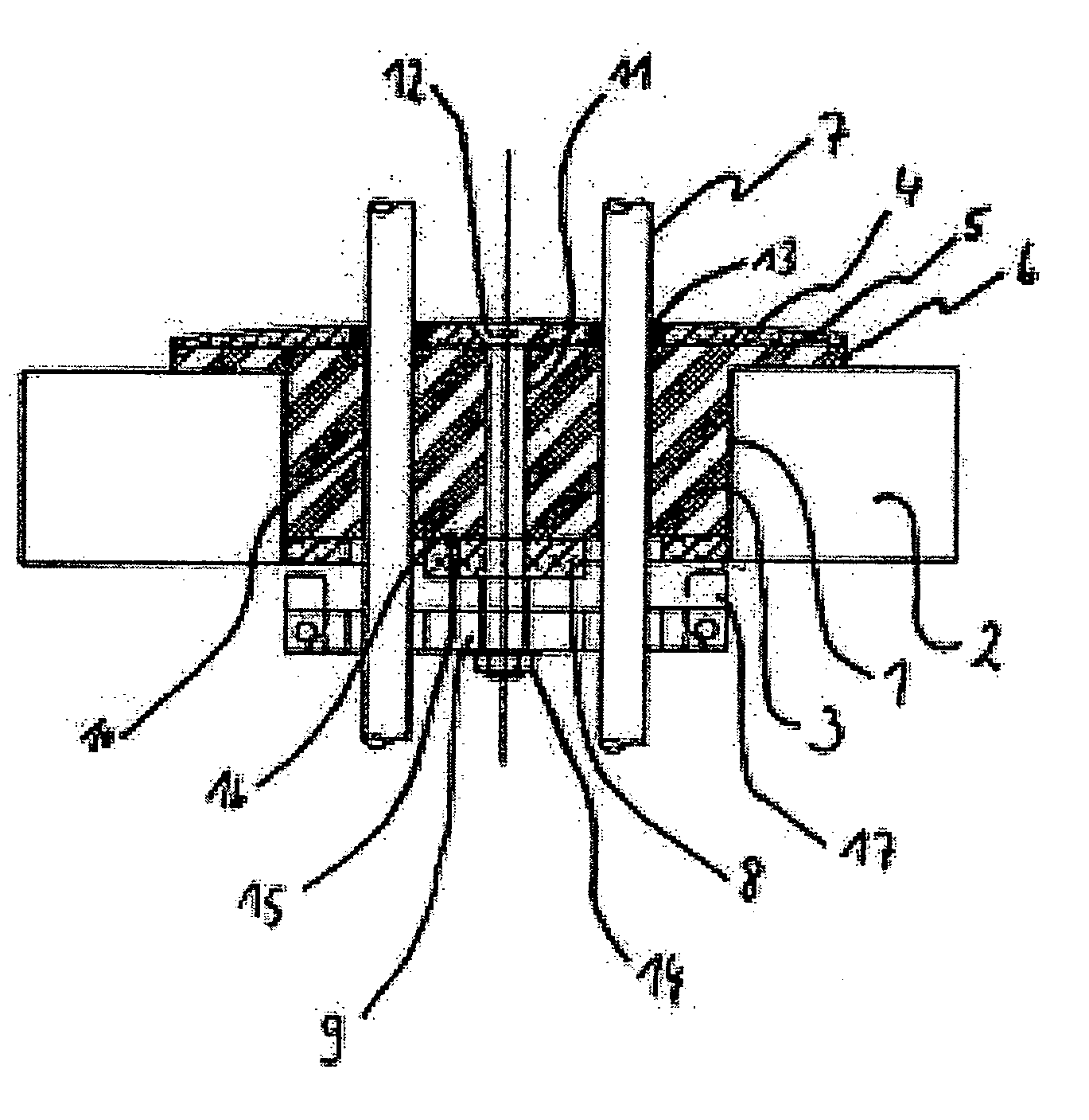
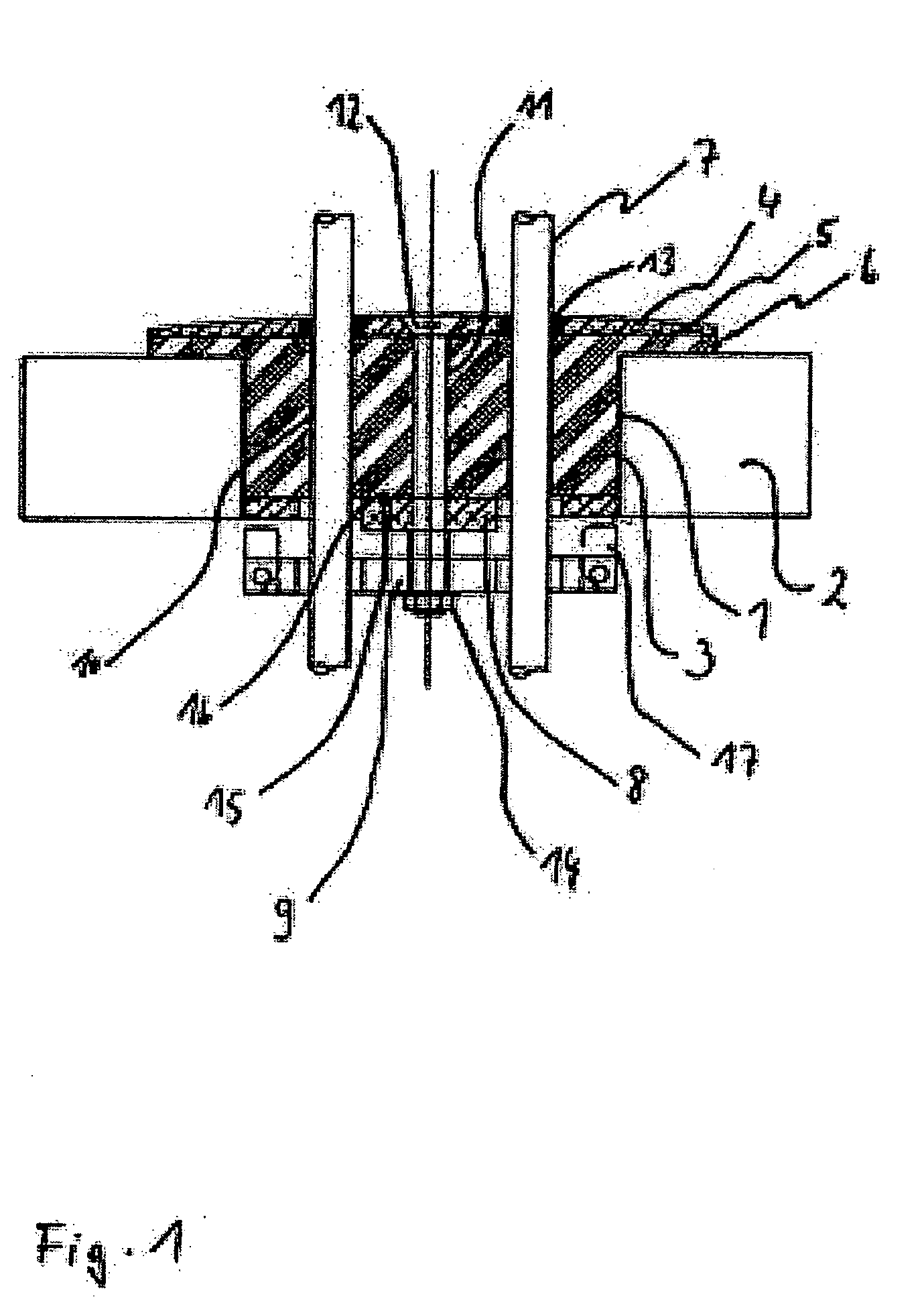
[0019]FIG. 1 shows an uninstalled fitting according to the invention that, which is completely inserted into an opening 1 for installing a cable leadthrough in a solid surface 2, which solid surface can be gripped from the back. The opening 1 is realized in the form of a bore in the floor of an on-board kitchen in an aircraft. A largely cylindrical rubber block 3, as an elastic moulded element, is connected with a circular upper boundary plate 4 by vulcanization. The diameter of the section of the rubber block 3 that extends into the bore 1 in the floor of the kitchen is slightly smaller than the diameter of the opening 1. The upper boundary plate 4 has a diameter that is significantly larger than the leadthrough opening 1. Consequently, the edge region of the circular upper boundary plate 4 forms a peripheral support region 5, in which the upper boundary plate 4 can be pressed against the floor. In the contact region with the upper boundary plate 4, the rubber block 3 contains a wi...


PUM


Abstract

The invention relates to a fitting for a liquid-tight cable leadthrough in an opening (1) in a solid surface (2), which solid surface can be gripped from the back, wherein said fitting comprises an upper boundary plate (4) that covers the opening (1), an elastic moulded element (3) that flatly contacts and is connected to the upper boundary plate (4) and can be at least partially inserted into the opening (1), a lower boundary plate (8) that can be lead through the opening (1), wherein the lower boundary plate flatly contacts and is connected to the elastic moulded element (3) on the opposite side of the elastic moulded element (3) referred to the upper boundary plate (4), a locking plate (9) that can be moved relative to the lower boundary plate (8) and is providable with at least two pivoted locking elements (17), wherein said locking elements are supported between pairs of mounting limbs (20) by element of a bolt (22) and can be pivoted between a position in which the locking plate (9) can be lead through the opening (1) and a stopping position which they enables a gripping from the back of the solid surface (2), at least one clamping element for adjusting the spacing between the upper boundary plate (4) and the locking plate (9) against forces generated during a deformation of the elastic moulded element, and opening (10) that extends through the locking plate (9), the boundary plates (4, 8) and the elastic moulded element (3) and serves for accommodating a cable (7) to be lead through the solid surface (2).

Description

REFERENCE TO RELATED APPLICATIONS [0001] This application claims the benefit of the filing date of U.S. Provisional Patent Application No. 60 / 602,700 filed Aug. 19, 2004, and of the German Patent Application No. 10 2004 040 293.0 filed Aug. 19, 2004 the disclosures of which are hereby incorporated herein by reference.FIELD OF THE INVENTION [0002] The invention relates to a fitting for a liquid-tight cable leadthrough in solid surfaces, which solid surface can be gripped from the back. In this context, the term solid surfaces refers, among other things, to various self-supporting wall structures, ceiling structures or floor structures, as well as other partitioning elements and boundary elements. The fittings according to the invention can be advantageously utilized in all instances, in which a cable leadthrough needs to be quickly installed and a sufficient sealing effect as well as an adequate strain relief needs to be ensured. TECHNOLOGICAL BACKGROUND [0003] Fittings of this type ...

Claims


Application Information

Patent Timeline
IPC IPC(8): H01R4/24
CPCH02G3/088Y10T16/063H02G15/013H02G3/22
Inventor MOTZIGKEIT, DANIEL
Owner AIRBUS OPERATIONS GMBH
Why Eureka
Try Eureka