Sports simulation system

a simulation system and sports technology, applied in the field of entertainment systems, can solve the problems that the simulation system cannot provide “true to life” sports experiences, and achieve the effect of enhancing the sports experience and facilitating the development of sports

Inactive Publication Date: 2006-03-23
RICHARDSON TODD E +2
View PDF16 Cites 63 Cited by
  • Summary
  • Abstract
  • Description
  • Claims
  • Application Information

AI Technical Summary

Benefits of technology

[0026] The sports simulation system provides advantages in that since the positions, velocity, acceleration and spin of the launched projectile are determined generally continuously as the launched projectile moves through the fields of view of the camera devices, the flight of the launched projectile can be simulated more accurately. This of course results in a more realistic sports experience. The sports simulation system also provides advantages in that virtually any type of projectile may be tracked avoiding the need for a specialized projectile. In addition, the projectile may be launched at the projectile tracking apparatus from a variety of positions providing greater flexibility and enhancing the sports experience.

Problems solved by technology

Although the above references show sports simulation systems that capture images of launched projectiles and use the image data to simulate the flights of the launched projectiles, these sports simulation systems fail to provide “true to life” sports experiences as a result of the mechanisms used to track the path of the launched projectiles.

Method used


Image

  • Sports simulation system
  • Sports simulation system
  • Sports simulation system

Examples


Embodiment Construction

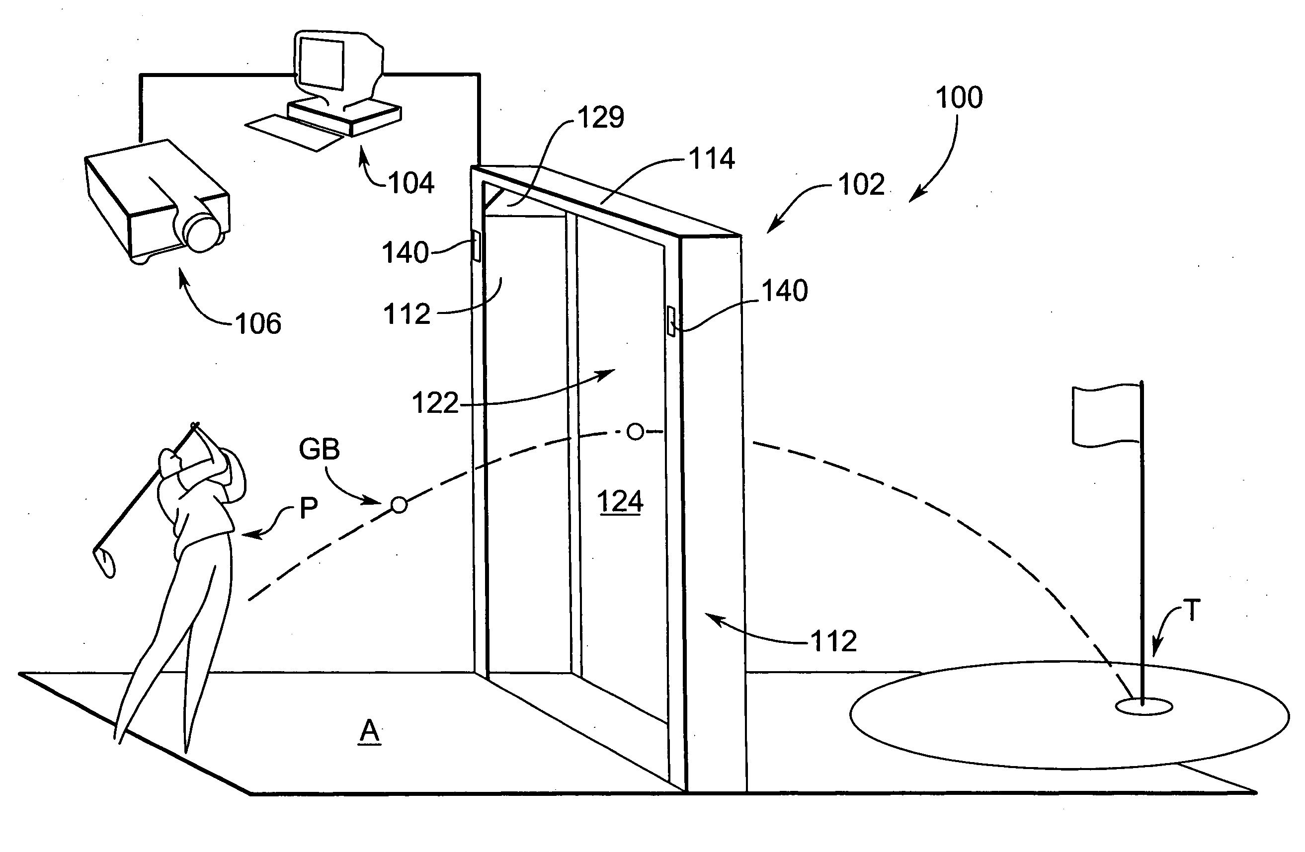
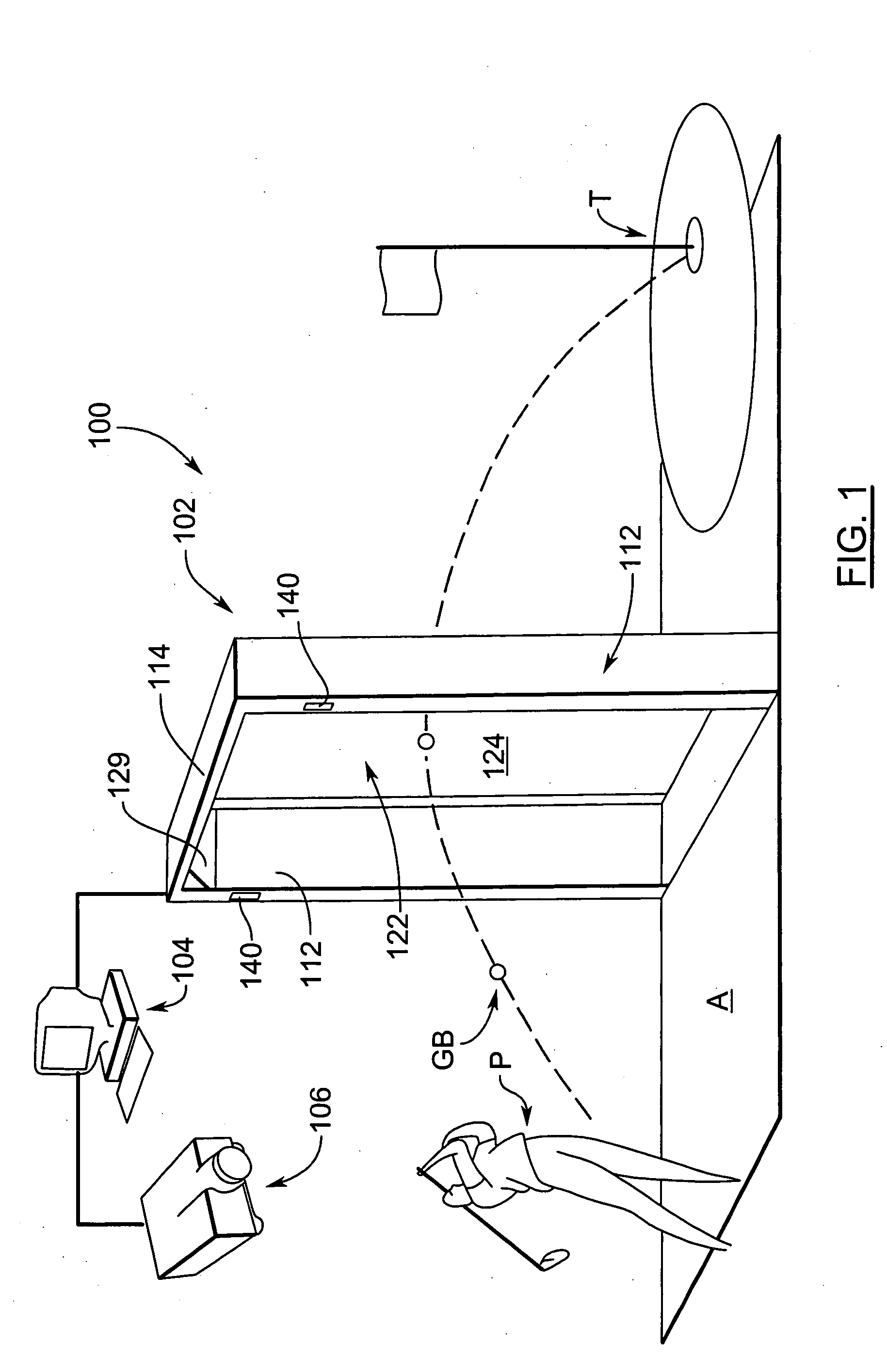
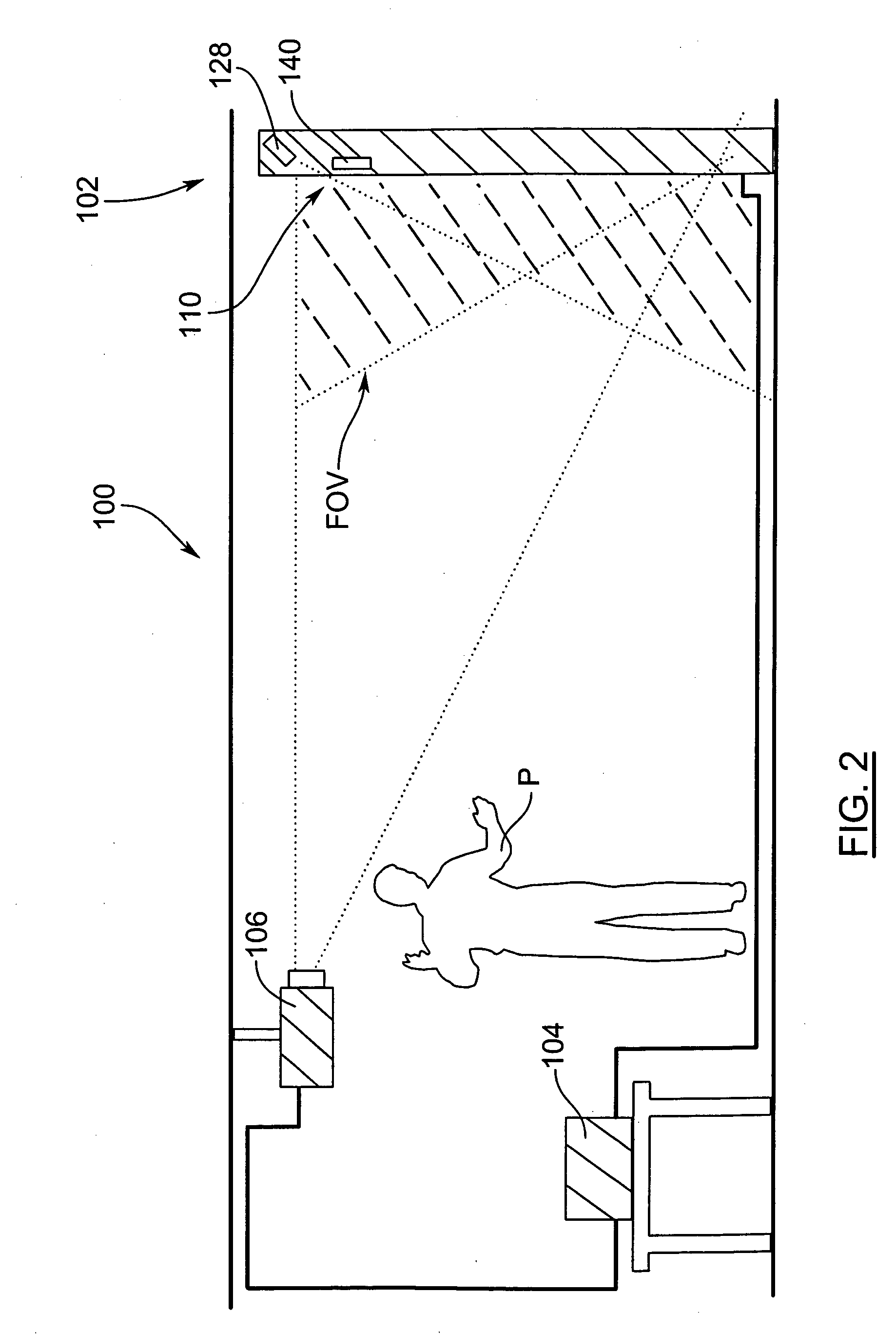
[0037] Turning now to FIG. 1, a sports simulation system is shown and is generally identified by reference numeral 100. As can be seen, sports simulation system 100 includes a projectile tracking apparatus 102 disposed in front of a player area A in which a player P stands. A host computer 104 is coupled to the projectile tracking apparatus 102 via a high-speed serial data link and to a ceiling mounted front video projector 106 that is aimed at the projectile tracking apparatus 102. The computer 104 outputs video image data to the projector 106, which in turn projects a video sequence on the projectile tracking apparatus 102. The video sequence portrays a visually apparent three-dimensional sports scene including a target T at which a projectile is to be launched. In this embodiment, the sports simulation system 100 simulates golf and thus, the three-dimensional sports scene is golf related and includes an image of a golf course hole, practice range etc. The projectile to be launche...


PUM


Abstract

A sports simulation system includes a projectile tracking apparatus having a display surface on which a visually apparent three-dimensional sports scene is presented. The projectile tracking apparatus captures images of a projectile tracking region disposed in front of the display surface to detect a launched projectile traveling through the projectile tracking region towards the display surface. At least one processing stage communicates with the projectile tracking apparatus and is responsive to the data received from camera devices to determine the three-dimensional positions, velocity, acceleration and spin of a detected projectile traveling through the projectile tracking region. The determined three-dimensional positions, velocity, acceleration and spin are used by the at least one processing stage to calculate a trajectory of the launched projectile into the visually apparent three-dimensional sports scene. Updated image data is generated by the at least one processing stage that includes a simulation of the launched projectile into the visually apparent three-dimensional sports scene following the calculated trajectory. A projection unit coupled to the at least one processing stage receives the image data from the at least one processing stage and presents the visually apparent three-dimensional sports scene, including the simulation, on the display surface.

Description

RELATED APPLICATIONS [0001] This application is a continuation-in-part of U.S. patent application Ser. No. 10 / 629,945 filed on Jul. 30, 2003 for an invention entitled “Sports Simulation System”, the content of which is incorporated herein by reference.FIELD OF THE INVENTION [0002] The present invention relates generally to entertainment systems and in particular to a sports simulation system. BACKGROUND OF THE INVENTION [0003] Sports simulation systems designed to simulate sports experiences are well known in the art. In many conventional sports simulation systems, a player propels a sports projectile such as a ball, puck, arrow, dart, etc. at a target image presented on a display screen. The motion of the sports projectile is detected and imaged and an extrapolation of the trajectory of the sports projectile is made. The extrapolated trajectory is then used to determine a sports result. The displayed image is in turn updated to reflect the sports result thereby to provide the playe...

Claims


Application Information

Patent Timeline
Patent Type & Authority Applications(United States)
IPC IPC(8): A63F13/00A63F9/24A63B69/00A63B69/36F41J5/00
CPCA63B2207/02A63B2243/0029A63F13/10A63B69/3658A63B69/0002A63B69/002A63B69/0026A63B2071/0691A63B2220/35A63B2225/20A63B2225/02F41J5/10A63B2024/0034A63B2220/70A63B2220/13A63B24/0021A63F2300/64A63F2300/8011A63B69/3623A63B2220/05A63B24/0084A63B2243/007A63B71/0622A63F2300/646A63B2071/0638A63B2220/806A63B2024/0031A63B2220/30A63B2220/40A63F2300/1087A63B2102/32A63B2225/74A63F13/45A63F13/573A63F13/812A63F13/213
Inventor RICHARDSON, TODD E.DAWE, WAYNEZHAO, ZUQIANG
Owner RICHARDSON TODD E
Why Eureka
Try Eureka