End configuration for a baseball bat

a baseball bat and configuration technology, applied in the field of end configuration of baseball bats, can solve the problems of adding a significant amount of pressure drag, and achieve the effects of reducing aerodynamic drag, increasing bat velocity, and reducing drag

Active Publication Date: 2006-03-23
NIKE INTERNATIONAL LTD
View PDF17 Cites 8 Cited by
  • Summary
  • Abstract
  • Description
  • Claims
  • Application Information

AI Technical Summary

Benefits of technology

[0012] The present invention is generally directed to the reduction of aerodynamic drag that acts on a swung baseball bat. The reduction in drag, for a given swinging force, will have the effect of increasing the bat velocity, thereby increasing the momentum that is imparted to the struck ball. The ball will thus travel farther than it would when struck with a less aerodynamic (hence, lower-momentum) bat that is swung with the same force.

Problems solved by technology

Such low-pressure regions near the trailing side of an object add a significant amount of pressure drag.

Method used


Image

  • End configuration for a baseball bat
  • End configuration for a baseball bat
  • End configuration for a baseball bat

Examples


embodiment 22

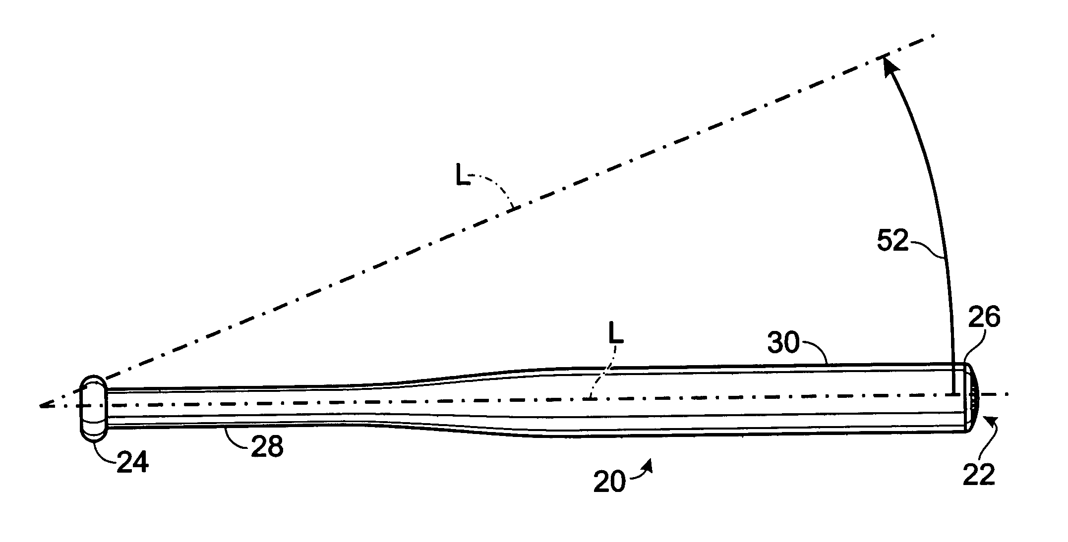
[0030] In the following description preferred and alternative embodiments of the invention are described as end caps, which may be manufactured separately from the remainder of the bat and subsequently attached to the free end of the bat. As noted above, however, the present invention may also be adapted for use with a single-piece or solid bat, integrally formed with the bat or otherwise fastened thereto. Accordingly, the following references to the inventive end configuration will hereafter be to an end cap embodiment 22, with the understanding that the configuration is not limited to use only with end caps.

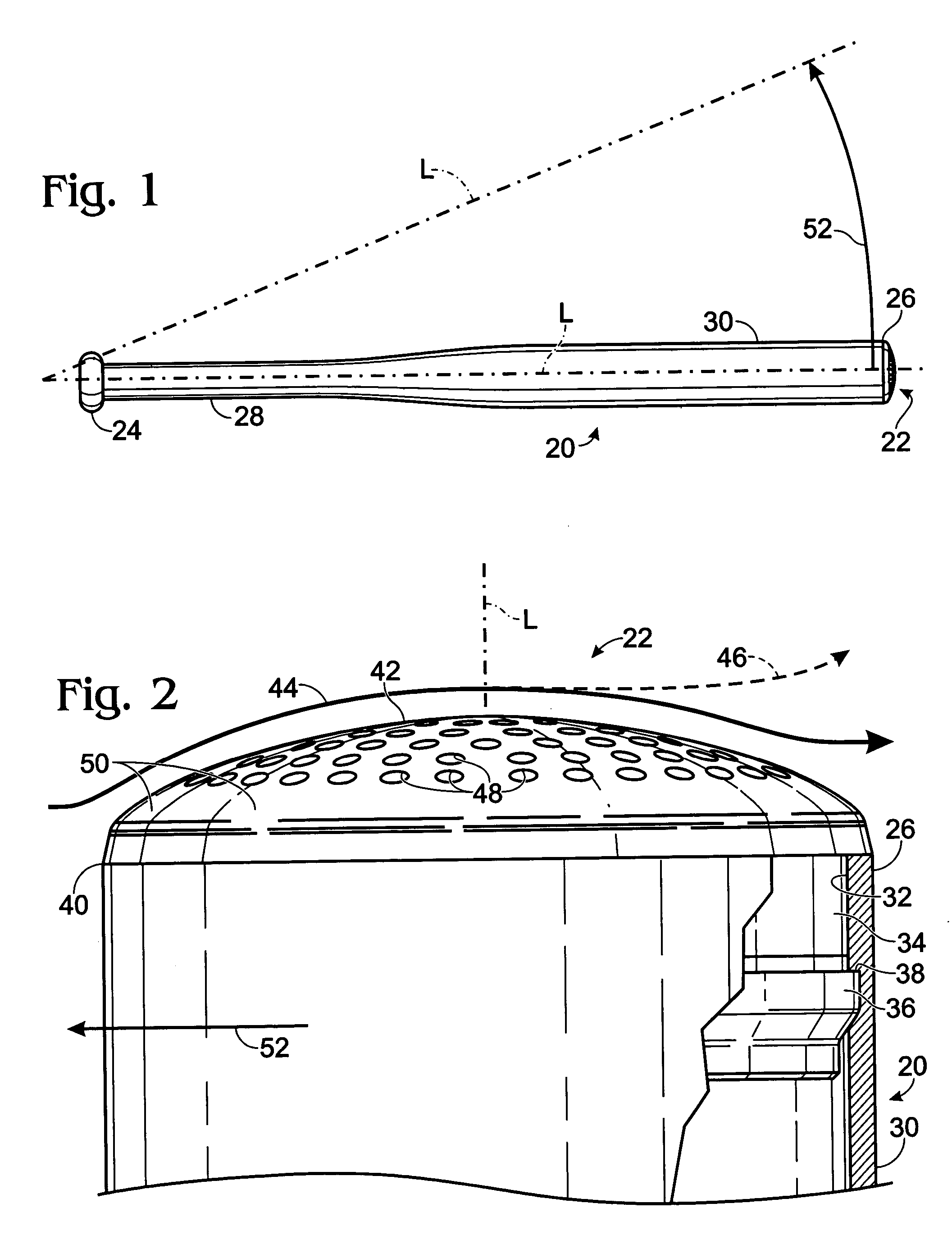
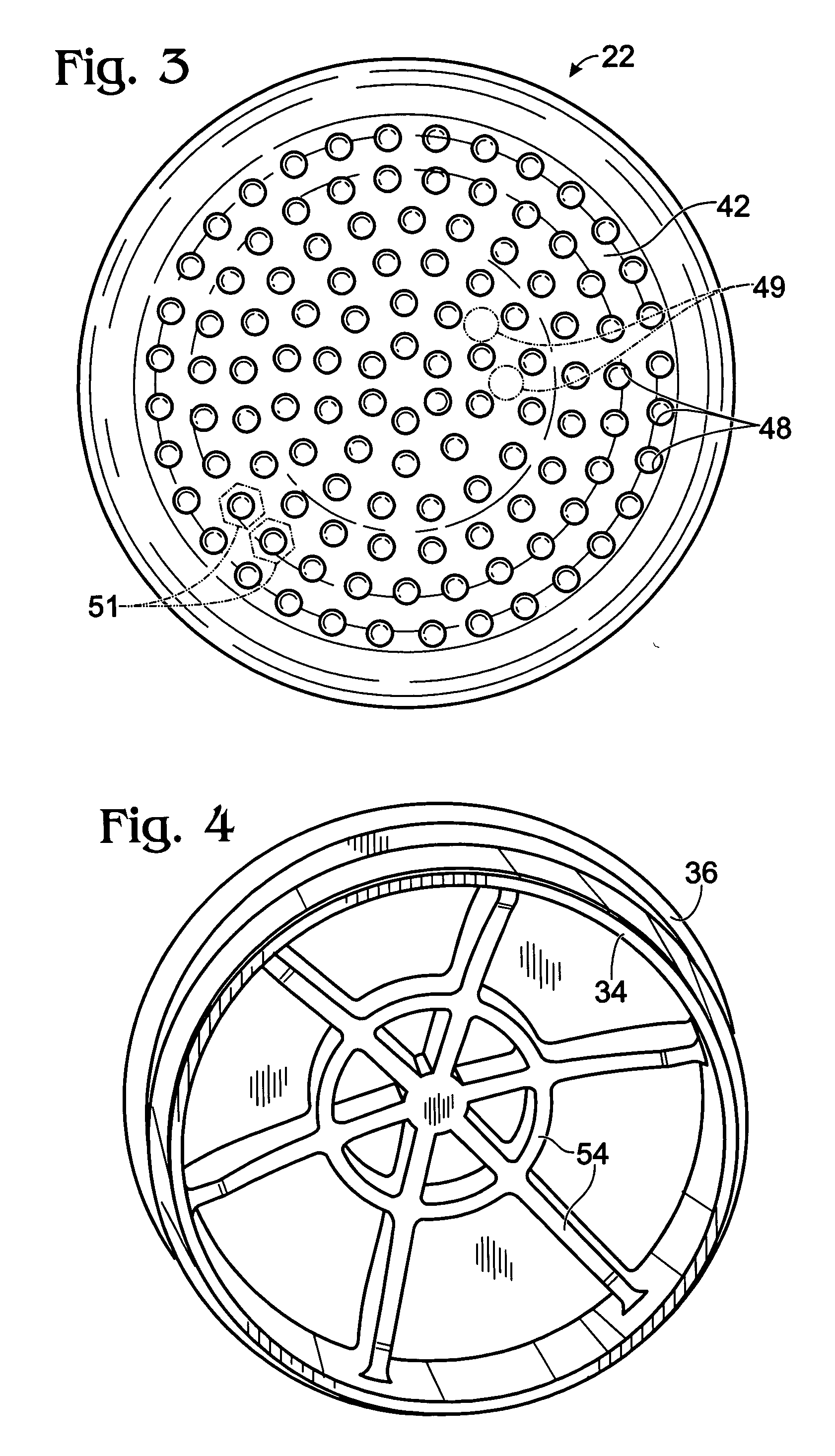
[0031] As shown in FIG. 2, the end cap 22 is attachable to the open, free end 26 of the bat. The bat 20 is preferably formed of an aluminum alloy and is hollow at that end 26. The open end 26 thus defines a cylindrical aperture 32 into which the base 34 of the end cap 22 snugly fits. The end cap 22 can be made from any suitable material such as lightweight metal, plastic, or co...

embodiment 322

[0045] It is also contemplated that a bat end configuration in accordance with the present invention may have enhanced streamlining, as discussed next in connection with the end cap embodiment 322 illustrated in FIG. 7. Specifically, the end cap 322 of this embodiment is intended to be “directional,” in the sense that the bat (and attached end cap 322) is held in a particular way so that when swung (such that the bat end moves from right to left in FIG. 7), one edge (a leading edge 346) of the end cap will lead the end cap through the air, and the opposite edge of the end cap (the trailing edge 347) will trail. The bat is thus held at a particular orientation relative to a batter's hands, in much the same way wooden bats are held (“label up”) so that as the bat nears the ball it is swung in a plane roughly parallel to the grain of the wood of the bat.

[0046] With a leading edge 346 of an end cap 322 so designated, it can be appreciated that the contoured end surface 342 is made quite...


PUM


Abstract

An end configuration for a bat includes in one embodiment an end cap that has a base that is shaped to fit within the open end of the bat thereby to attach the end cap to the bat. The end cap also includes a convexly contoured end surface that is exposed when the end cap is attached to the bat. The end surface is roughened to reduce the aerodynamic drag when the bat is swung, thereby to increase the momentum of the bat for a given amount of force applied to swing the bat.

Description

TECHNICAL FIELD [0001] This invention relates to an end configuration for a baseball bat. The configuration reduces aerodynamic drag that acts on the bat when the bat is swung. BACKGROUND [0002] It is well known that a baseball bat is used for striking a ball during the game of baseball. The bat may be used with a conventional hardball or with a larger ball that is known as a softball. For the purposes of this description, the terms bat, ball, and baseball are used in their generic sense, and the invention described below may be adapted for use in any sport where an elongated member such as a bat is swung for the purpose of striking an object such as a ball. [0003] The action of striking a baseball with a bat changes the momentum of the ball. Much of the momentum of the bat is thus transferred to the ball. [0004] The momentum of the swung bat is the product of the mass of the bat and its velocity. The velocity of the bat primarily depends upon how much force a batter applies to the ...

Claims


Application Information

Patent Timeline
Patent Type & Authority Applications(United States)
IPC IPC(8): A63B59/00A63B59/06A63B59/18
CPCA63B2059/0011A63B59/06A63B2102/18A63B59/50A63B60/006A63B59/56
Inventor PAGE, CHRISTOPHER S.BROWNLIE, LEONARD W.OSTAFICHUK, PETER M.
Owner NIKE INTERNATIONAL LTD
Why Eureka
Try Eureka