Friction stir welding method and apparatus

a technology of friction stir and welding method, which is applied in the direction of soldering apparatus, welding devices, manufacturing tools, etc., can solve the problems of effective control of the degree of heating and softening of the place, and achieve the effect of efficient fsw, efficient welding, and easy softening

Inactive Publication Date: 2006-03-30
MITSUBISHI HEAVY IND LTD
View PDF12 Cites 37 Cited by
  • Summary
  • Abstract
  • Description
  • Claims
  • Application Information

AI Technical Summary

Benefits of technology

[0029] (1) As the invention of Claim 1 employs the above-mentioned first means, the portion of the metal members surrounding the probe is heated and the contact portion of the metal members with the probe that is softened by the frictional heat of the rotating probe of the FSW tool and stirred by the probe can be more appropriately and easily softened.
[0030] (2) As the invention of Claim 2 employs the above-mentioned second means, in addition to the effect of the invention of Claim 1, by providing the heating means effecting the electromagnetic induction heating, the weld portion to be welded by the FSW is heated by the electromagnetic induction heating. Also, by employing the probe and rotator of the FSW tool made of a non-conductive material, the probe and rotator that rotate at a high speed are in no case heated by the electromagnetic induction and a strength deterioration caused in, or a thermal influence acting on, an upper drive portion of the FSW tool or other supporting portions can be avoided.
[0031] (3) As the invention of Claim 3 employs the above-mentioned third means, in addition to the effect of the invention of Claim 2, by providing the heating means concentrically with the FSW tool, the weld portion frictionally stirred by the probe can be concentrically heated. Also, even in the case where the welding direction (moving direction of the probe) is bent windingly or like a U-shape, the heating at the weld portion becomes uniform and an efficient welding can be carried out.
[0032] Further, by the electromagnetic wave shielding means, no bad influence, such as heat generation or strain by heat, is given on the surrounding metal-made parts and components.
[0033] (4) As the invention of Claim 4 employs the above-mentioned fourth means, in addition to the effect of the invention of any one of Claims 1 to 3, the heating temperature is measured by the temperature measuring means and by controlling the output of the heating means based on the measured value of the heating temperature, an efficient FSW can be carried out.
[0034] (5) As the invention of Claim 5 employs the above-mentioned fifth means, in addition to the effect of the invention of any one of Claims 1 to 3, the rotational state of the probe is measured and by controlling the output of the heating means so as to be increased when the revolution of the probe is decreased or when the current rotating the probe is increased, an efficient FSW can be carried out.

Problems solved by technology

That is, there is a problem that the bone member must be selected corresponding to the diameter of the probe.
Nevertheless, the methods of the above-mentioned Patent Documents 1 and 2 are no more than for the purpose that the pre-heating is done for shortening the treatment time of the FSW method and the post heating is done for enhancing the quality after the treatment and there are problems such that places to be heated are distant from the place where the FSW is being carried out so that an effective control of the degree of heating and softening of the place where the FSW is being carried out is difficult, a large power (electric power) is needed for driving the FSW tool and a large FSW tool that is more than needed must be used.

Method used


Image

  • Friction stir welding method and apparatus
  • Friction stir welding method and apparatus
  • Friction stir welding method and apparatus

Examples


first embodiment

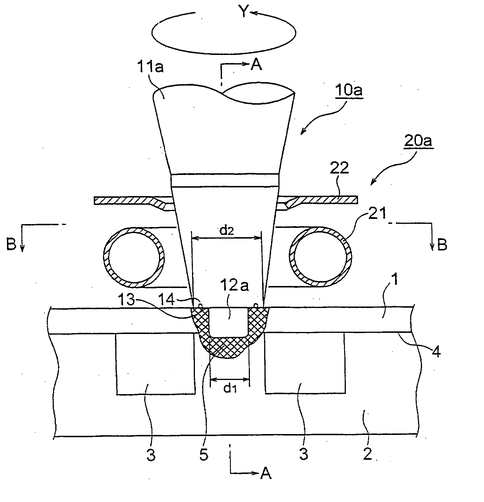
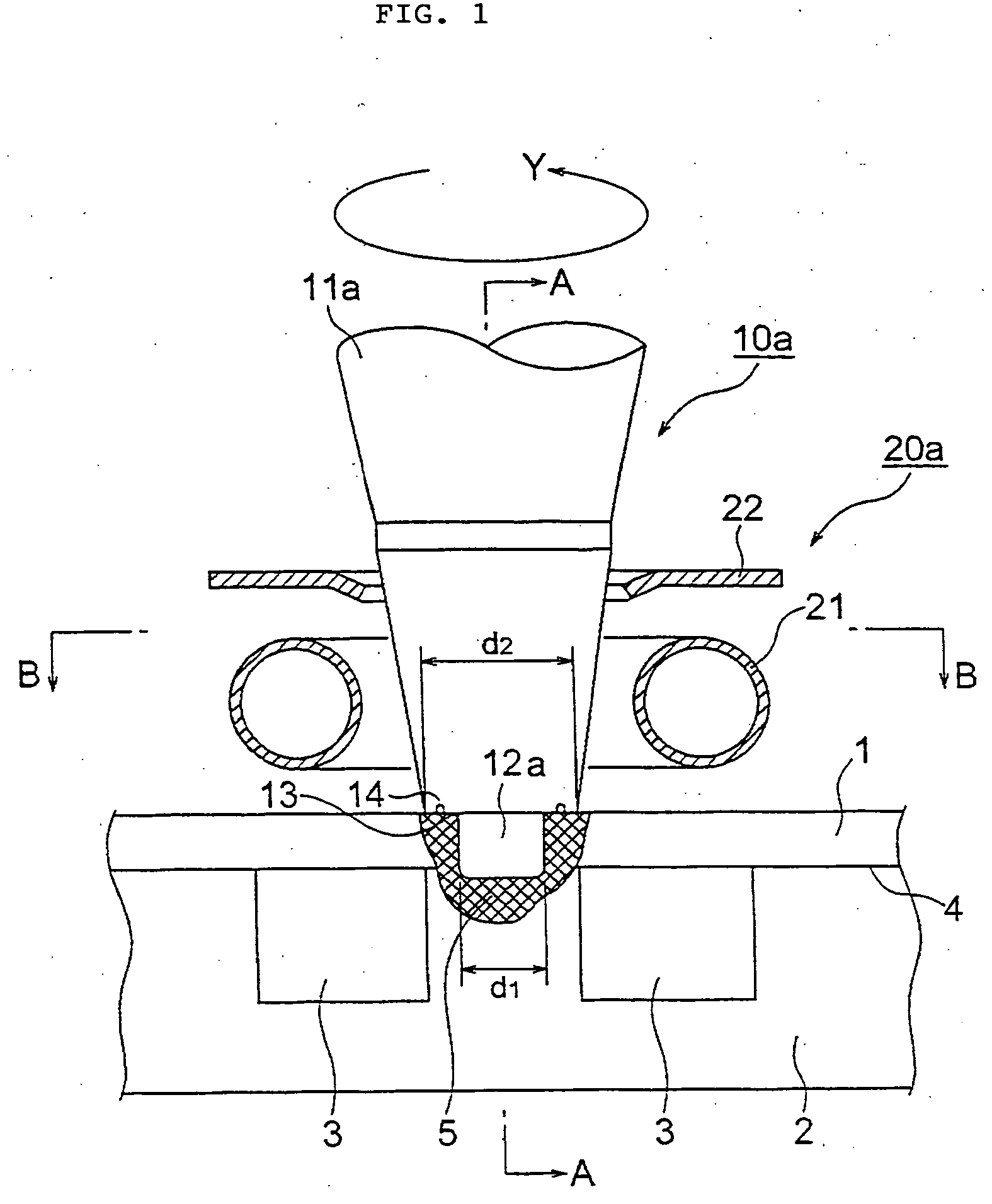
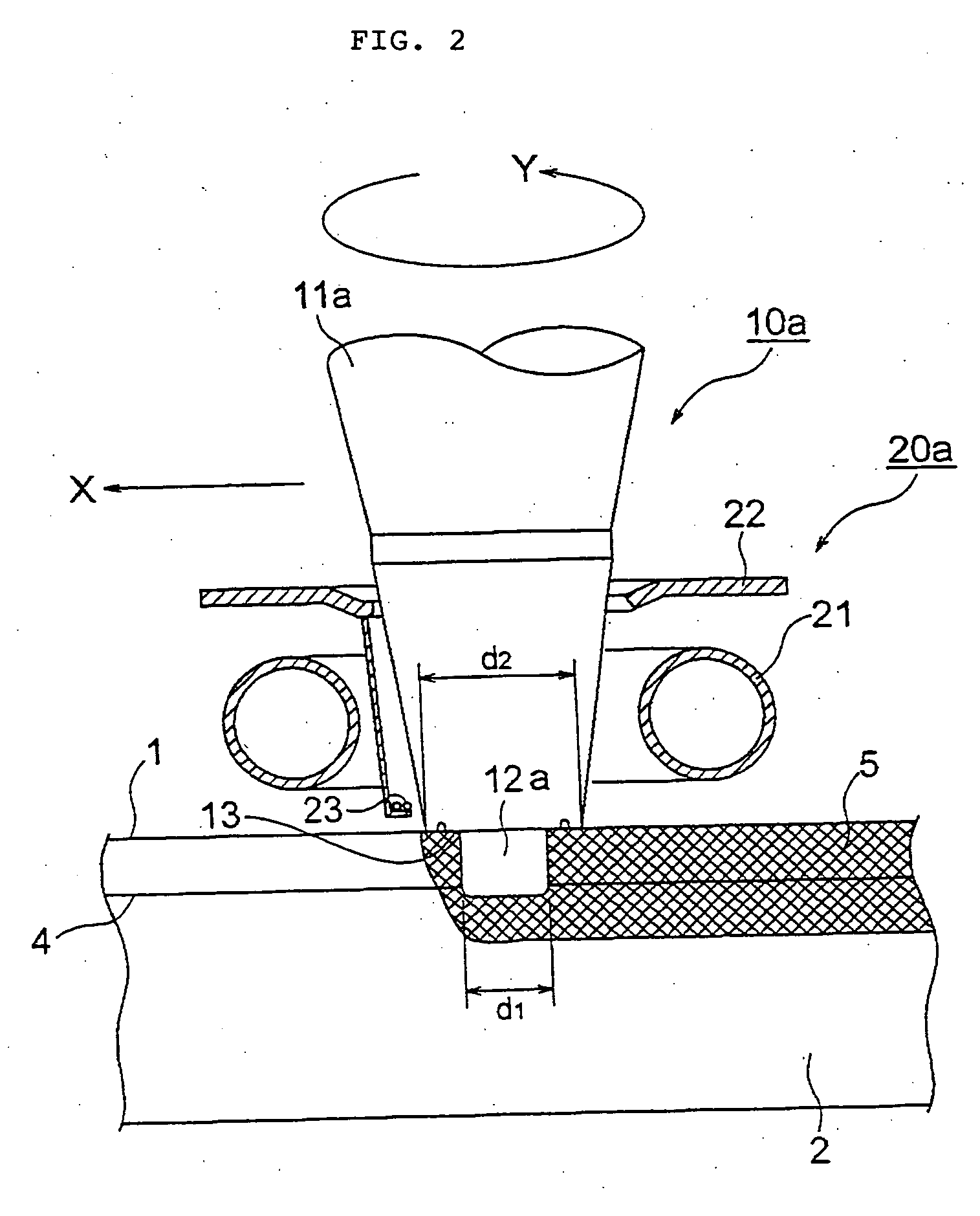
[0058]FIG. 1 is a cross sectional front view showing a state that a FSW tool of the present invention performs a welding work, FIG. 2 is a cross sectional view taken on line A-A of FIG. 1 and FIG. 3 is a cross sectional view taken on line B-B of FIG. 1. FIG. 4 is a control diagram of the FSW tool of FIG. 1.

second embodiment

[0059]FIG. 5 is a cross sectional front view showing a state that a FSW tool of the present invention performs a welding work and FIG. 6 is a cross sectional view taken on line C-C of FIG. 5.

third embodiment

[0060]FIG. 7 is a cross sectional front view showing a state that a FSW tool of the present invention performs a welding work and FIG. 8 is a cross sectional view taken on line D-D of FIG. 7.

[0061]FIG. 9 is a perspective view showing one example of an integrated piping plate that is appropriate to be welded by the FSW tools of the embodiments of the present invention.

[0062] First, an example of a structure of an integrated piping plate that is appropriate to be welded by the FSW will be described with reference to FIG. 9.

[0063] As shown there, the integrated piping is constructed by an upper plate 1 and a lower plate 2, and a plurality of connectors 9 or the like of a device, such as a device of a fuel cell power generating system or the like, are arranged on a surface of the upper plate 1.

[0064] Each of the connectors 9 is fixed to an integrally formed plate-like unit of the upper and lower plates 1, 2, welded together by the FSW, via a plurality of stud bolts 7 and nuts 8 or th...


PUM

PropertyMeasurementUnit
temperatureaaaaaaaaaa
non-conductiveaaaaaaaaaa
temperatureaaaaaaaaaa

Abstract

Friction stir welding (FSW) method and apparatus are provided by which power needed for the FSW is reduced and a compact FSW tool can be used. In the FSW method comprising the steps of lapping metal members one on another and inserting a rotating probe of a FSW tool into a contact portion of the metal members making contact with the probe so that the contact portion is softened by frictional heat and stirred by the probe and the metal members are welded together, a portion of the metal members surrounding the probe is heated by a heating means.

Description

BACKGROUND OF THE INVENTION [0001] 1. Field of the Invention [0002] The present invention relates to a friction stir welding method and apparatus by which a conductive material, such as aluminum (including aluminum alloy) or the like, and other magnetic materials are welded by a friction stir welding (hereinafter the friction stir welding is referred to as “FSW”). [0003] 2. Description of Related Art [0004] In every case of a conventional FSW method, a frictional heat is made use of such that a FSW tool comprises a probe and a shoulder portion and while the probe is inserted into a weld portion to be welded by the FSW and the shoulder portion is urged against members, such as metal members, to be welded (hereinafter referred to as “weld object members”), the FSW tool is rotated. For this reason, the FSW tool is needed to have a strong rigidity so as to withstand the urging force. Also, a large power is needed so that the FSW tool is forcibly rotated so as to maintain the friction. [...

Claims


Application Information

Patent Timeline
Patent Type & Authority Applications(United States)
IPC IPC(8): B23K31/02B23K20/12B23K
CPCB23K20/1265B23K20/1235
Inventor ISHIKAWA, SOICHIROHIDAKA, HARETARO
Owner MITSUBISHI HEAVY IND LTD
Why Eureka
Try Eureka