Refractive index changing apparatus and method

a technology of index changing apparatus and refractive index, which is applied in the direction of instruments, optical elements, optics, etc., can solve the problem of limited use of liquid crystals

Active Publication Date: 2006-03-30
KK TOSHIBA
View PDF3 Cites 39 Cited by
  • Summary
  • Abstract
  • Description
  • Claims
  • Application Information

AI Technical Summary

Benefits of technology

[0015] injecting the electrons into the ground level of each quantum dot utilizing a tunneling effect, or preventing the electrons from being injected into the ground level of each quantum dot by varying an energy level of an injection unit for injecting electrons into the quantum dots, via a barrier structure unit formed of a dielectric which surrounds the quantum dots.

Problems solved by technology

Although liquid crystal achieves a change of about 10% in refractive index, the use of liquid crystal is limited because it is a liquid.

Method used


Image

  • Refractive index changing apparatus and method
  • Refractive index changing apparatus and method
  • Refractive index changing apparatus and method

Examples


experimental example 1

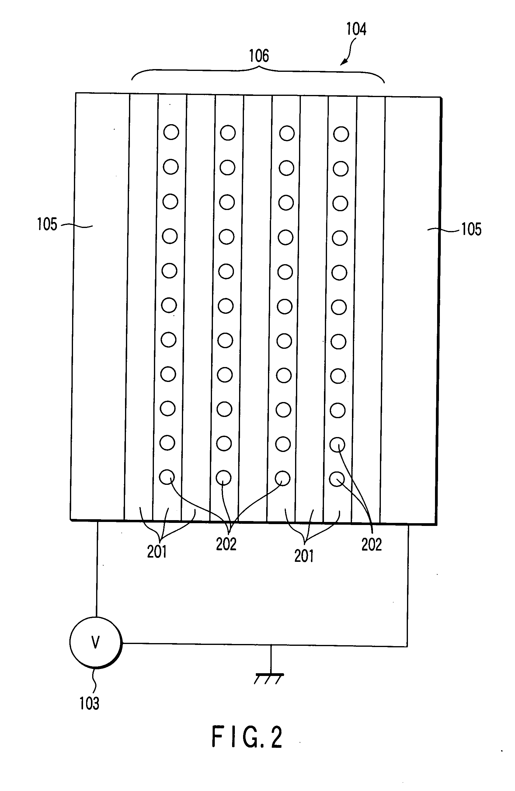
[0080] Referring to FIG. 6, a description will be given of a specific experimental example in which the refractive index changeable element structure 104 is modified.

[0081] In this example, the barrier structure 201 is formed of polystyrene films, and the quantum dots 202 are formed of C60 and dispersed in the polystyrene films. The polystyrene films containing the quantum dots 202 are stacked and held between the ITO transparent electrodes 105. To permit the potential difference of the ITO transparent electrodes 105 to be changed, each electrode (electron injection unit) 105 is connected to the energy level control unit 103 for the electron injection unit. In the refractive index changeable element structure shown in FIG. 6, ten units, each of which is formed of the transparent electrodes 105 and the polystyrene films held therebetween, are attached together.

[0082] As shown in FIG. 6, voltages were applied to the respective pairs of ITO transparent electrodes 105 so that the elec...

experimental example 2

[0087] In the experimental example 1, if the ITO transparent electrodes as the electron injection unit were formed of gold, when the application of the voltage was stopped, the refractive index pattern disappeared. However, when the ITO transparent electrodes were formed of cesium, the pattern was left even after the application of the voltage was stopped.

experimental example 3

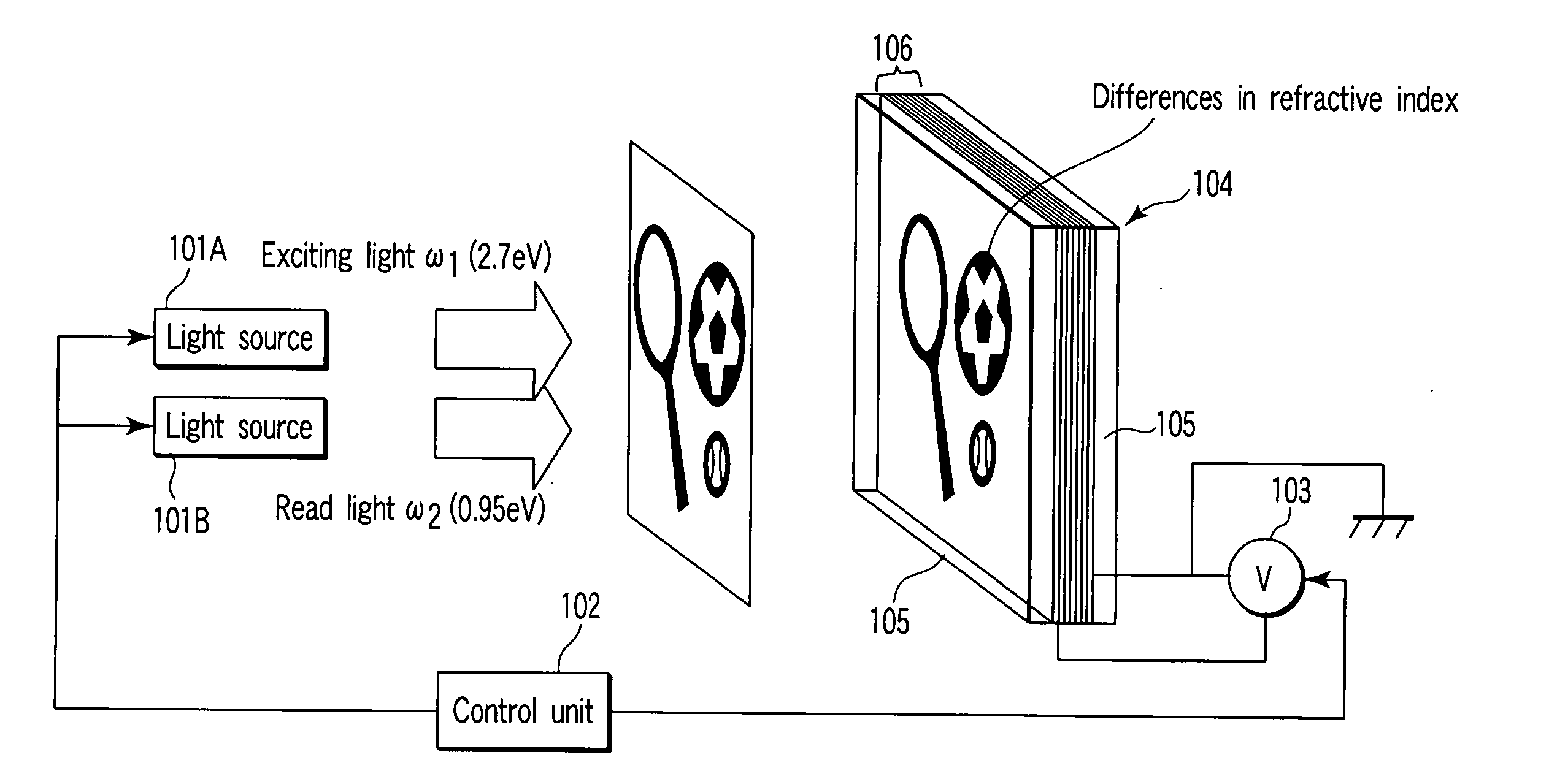
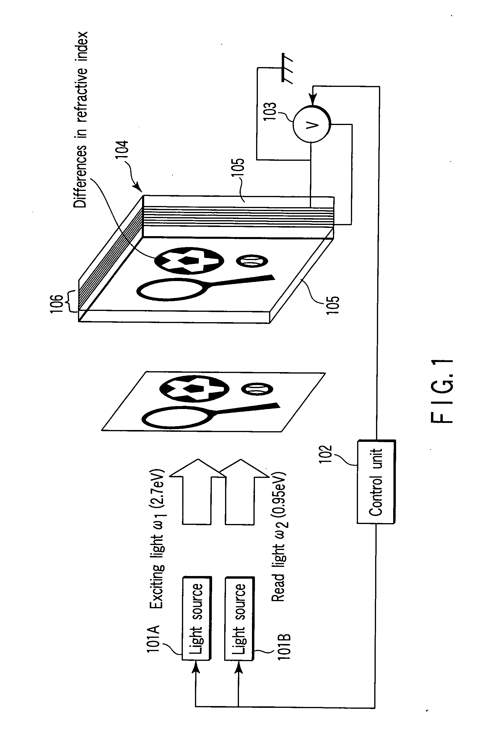
[0088] In a third experimental example, two exciting light beams are made to interfere with each other by an object lens, and the resultant interference pattern is recorded in the quantum structure 106. This example will be described with reference to FIG. 8.

[0089] Two exciting light beams ω3 and ω4 (each having an energy level of 2.7 eV and a wavelength of about 460 nm) were made to interfere with each other by an object lens 501. The resultant light beam was emitted to the refractive index changeable element structure of the experimental example 1, whereby a light spot of an interference pattern was recorded in the quantum structure 106. This recording corresponds to recording of digital data. The density of the interference pattern was about 9 patterns per 1 cm2. After that, when a light beam (read light beam) of 0.95 eV (with a wavelength of 1.3 μm) was emitted with a beam area of 1 cm2 from the light source 101B, the light beam was diffracted at 9 points, thereby simultaneousl...


PUM

PropertyMeasurementUnit
energy gapaaaaaaaaaa
transparentaaaaaaaaaa
de Broglie wavelengthaaaaaaaaaa

Abstract

Refractive index changing apparatus includes quantum dots each having discrete energy levels including ground level and excited level, the excited level being higher than the ground level even if energy due to ambient temperature is provided on the quantum dots, barrier structure unit formed of dielectric which surrounds the quantum dots, injection unit configured to inject an electron into position of the ground level in each quantum dot via the barrier structure unit, utilizing tunneling effect, or to prevent injection of an electron into the position, injecting the electron or preventing injection of the electron controlled by changing an energy level of the injection unit, source which emits, to the quantum dots, first light beam having first energy for exciting electrons from the ground level to the excited level, and source which emits, to the quantum dots, second light beam having second energy different from the first energy.

Description

CROSS-REFERENCE TO RELATED APPLICATIONS [0001] This application is based upon and claims the benefit of priority from prior Japanese Patent Application No. 2004-287960, filed Sep. 30, 2004, the entire contents of which are incorporated herein by reference. BACKGROUND OF THE INVENTION [0002] 1. Field of the Invention [0003] The present invention relates to a refractive index changing apparatus and method. [0004] 2. Description of the Related Art [0005] Many researchers have done so far research and development of refractive index changing materials (see, for example, Jpn. Pat. Appln. KOKAI Publication No. 2002-217488). This is because the refractive index determines the propagation characteristic of a light beam, therefore control of a light beam can be realized by controlling the refractive index and spatial distribution of refractive indices. Resulting from the success of the development of refractive index control techniques that utilize liquid crystal, liquid crystal displays hav...

Claims


Application Information

Patent Timeline
Patent Type & Authority Applications(United States)
IPC IPC(8): H01L33/00G02B26/02G02F1/01G02F1/017
CPCB82Y20/00G02F1/01716G02F2203/50G02F2001/01791G02F2001/0151Y10S977/774G02F1/0151G02F1/01791
Inventor TODORI, KENJIYOSHIMURA, REIKOAIGA, FUMIHIKOTADA, TSUKASA
Owner KK TOSHIBA
Why Eureka
Try Eureka