Non-leak pool fixture and method for implementing

a non-leak, pool technology, applied in swimming pools, pipe connection arrangements, mechanical equipment, etc., can solve the problems of voids of plaster behind the fittings, pre-existing leakage of prior art fittings used in cement shell pools, ponds and spas, and common leakage of premature leakage in fittings along the lower edge. , to achieve the effect of convenient implementation

Inactive Publication Date: 2006-03-30
YEAGER BRYAN KEITH +1
View PDF30 Cites 2 Cited by
  • Summary
  • Abstract
  • Description
  • Claims
  • Application Information

AI Technical Summary

Benefits of technology

[0016] The present invention is directed to leak resistant fittings and methods for installing same. It has long been understood that prior art fittings commonly used in cement shell type pools, ponds and spas are susceptive to premature leakage. The causes have largely gone undiscovered and thus improvements to these fittings that might prevent or resist leakage has eluded the prior art. The invention disclosed herein presents an eloquent solution to the shortcomings of prior art fittings in an economical and easily implemented form.

Problems solved by technology

It has long been understood that prior art fittings commonly used in cement shell type pools, ponds and spas are susceptive to premature leakage.
The causes have largely gone undiscovered and thus improvements to these fittings that might prevent or resist leakage has eluded the prior art.
Premature leaks commonly occur in those fittings along the lower edge of an exposed beauty ring.
The reason for the leakage is substantially due to uncured plaster migration.
During installation, uncured plaster behind the fitting siphons down the cement shell wall and away from the sidewall creating a cavity void of plaster behind the fitting.
The seal eventually fails due to water seepage around the beauty ring and into the cavity, resulting in an expensive repair for the owner.

Method used


Image

  • Non-leak pool fixture and method for implementing
  • Non-leak pool fixture and method for implementing
  • Non-leak pool fixture and method for implementing

Examples


Embodiment Construction

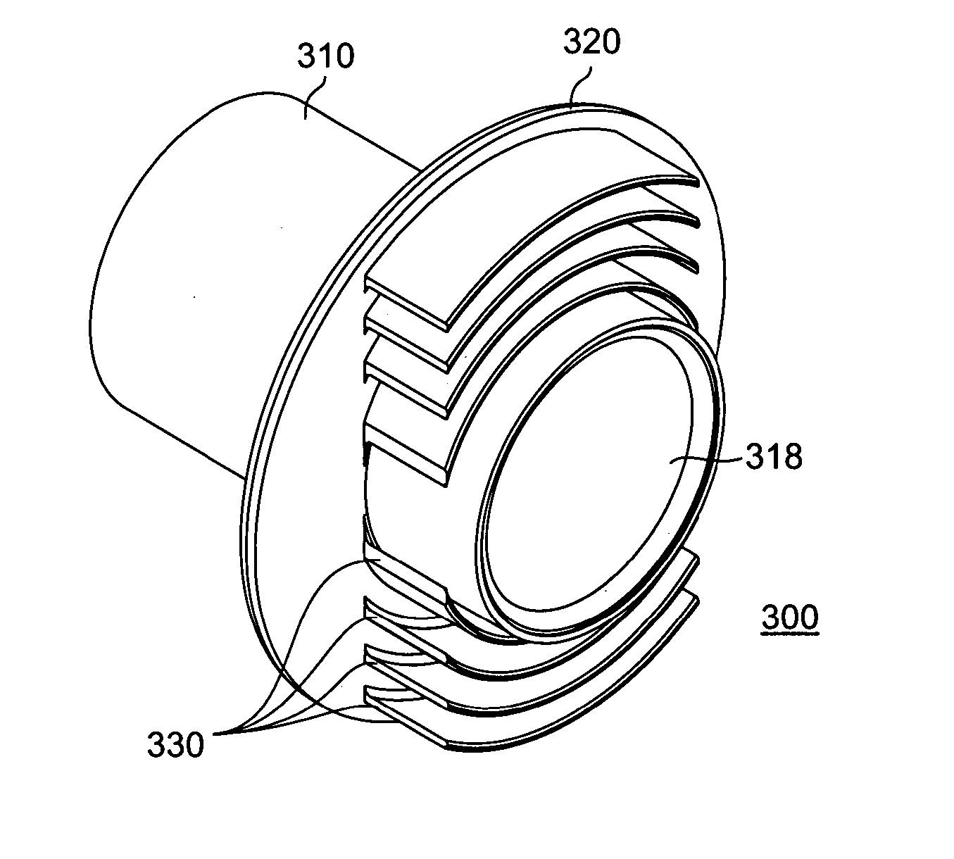
[0048] Wall fittings, for the purposes for describing the present invention, include any class of fixtures which traverse a wall or floor of a pool, spa or the like and terminates within an interior, or couples to a conduit which, in turn, traverses a wall or floor. Examples of pool fittings include sidewall body fittings such as inlet jets or aerators (directional such as eyeball wall inlet fitting or non-directional), sidewall returns, drains or suction fittings, rope anchors, light niches, suction strainers, swivel mounts, skimmers and other gravity assisted fittings such as overfill drains, main floor drains and the like. Fittings may be fabricated from PVC or ABS plastics, stainless steel, bronze, chrome or any other material that tend to resists the affects of the chemicals in the pool water and exposure to UV (ultraviolet) sun rays. For the purposes herein, a fitting may be further categorized as by whether or nor the fitting is cemented in position. Furthermore, the term “po...


PUM


Abstract

An improved sidewall fitting is disclosed with a fitting body and a flange disposed about the fitting body. Plaster catches disposed along a face of the flange and positioned approximately coextensively with the fitting body. The bodies of the plaster catches may be curvilinear-shaped or straight and the body portions may be of heights for aligned or off-setting configurations. The fitting is installed the plaster catches oriented directly below the body of the fitting, along a generally horizontal plane. Plaster is layered over the flange and plaster catches, and up to the opening in the fitting body. The plaster catches may be disposed along a posterior face of a flange, or simultaneously along the anterior and posterior faces. A second fitting type includes an extension surface for increased bonding with the plaster with additional surface area available for sealing with the plaster. Disposed onto the sealing surface is a leave-out strip, which protects the sealing surface during cementing. After removal of the leave-out strip, the sealing surface provides an uncontaminated surface on which a sealant may be liberally applied. Optionally, a seal may be provided on the sealing surface interposed between the leave-out strip.

Description

BACKGROUND OF THE INVENTION [0001] 1. Field of the Invention [0002] The present invention relates to wall fixtures for piping and the like. More particularly, the present invention relates to non-leak wall fixtures for installation in a aquatic environment such as pools, spas and the like. Even more particularly, the present invention relates to improved fitting designs which resist leaking and methods for installing the improved fitting designs. Still more particularly, the present invention relates to wall fittings and the like that rely on plaster for making a hydraulic seal and are typically installed with their bodies in a horizontal orientation and installation method for the fittings. [0003] 2. Description of Related Art [0004] The construction of an in-ground pool (or spa) may be accomplished through the use of various construction platforms of which fiberglass, vinyl-liner pools and cement, are the most commonly used in inground pools. Fiberglass, or Kevlar (a registered tr...

Claims


Application Information

Patent Timeline
Patent Type & Authority Applications(United States)
IPC IPC(8): F16L49/00
CPCE04G15/061E04H4/148E04H4/14
Inventor YEAGER, BRYAN KEITHSCHERLER, JOHN ROBERT
Owner YEAGER BRYAN KEITH
Why Eureka
Try Eureka